Toyota Tacoma (2015-2018) Service Manual: Terminals Of Ecu
TERMINALS OF ECU
FORWARD RECOGNITION CAMERA
NOTICE:
- DTCs may be output when connectors are disconnected during inspection. Therefore, be sure to clear the DTCs using the Techstream once the inspection has been completed.
- Do not apply excessive force to the forward recognition camera connector.
(a) Check forward recognition camera

|
Terminal No. (Symbol) |
Wiring Color |
Terminal Description |
Condition |
Specified Condition |
|---|---|---|---|---|
|
F46-7 (IGB) - Body ground |
BE - Body ground |
Power source |
Ignition switch ON |
11 to 14 V |
|
Ignition switch off |
Below 1 V |
|||
|
F46-10 (GND) - Body ground |
W-B - Body ground |
Ground |
Always |
Below 1 Ω |
|
F46-5 (CA1P) - Body ground |
L - Body ground |
CAN communication signal |
Ignition switch ON |
Pulse generation (Waveform 1) |
|
F46-11 (CA1N) - Body ground |
W - Body ground |
Pulse generation (Waveform 2) |
||
|
F46-6 (CANH) - Body ground |
B - Body ground |
Pulse generation (Waveform 1) |
||
|
F46-12 (CANL) - Body ground |
W - Body ground |
Pulse generation (Waveform 2) |
(b) WAVEFORM 1
(1) CAN communication signal
|
Item |
Content |
|---|---|
|
Terminal Name |
Between F46-5 (CA1P) and F46-10 (GND) Between F46-6 (CANH) and F46-10 (GND) |
|
Tester Range |
1 V/DIV., 10 ÎĽsec./DIV. |
|
Condition |
Ignition switch ON |
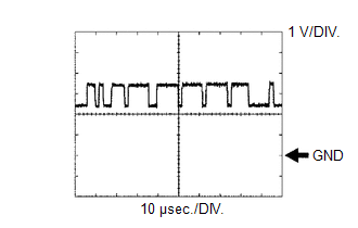
HINT:
The waveform varies depending on the CAN communication signal.
(c) WAVEFORM 2
(1) CAN communication signal
|
Item |
Content |
|---|---|
|
Terminal Name |
Between F46-11 (CA1N) and F46-10 (GND) Between F46-12 (CANL) and F46-10 (GND) |
|
Tester Range |
1 V/DIV., 10 ÎĽsec./DIV. |
|
Condition |
Ignition switch ON |
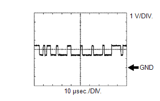
HINT:
The waveform varies depending on the CAN communication signal.
 Diagnosis System
DIAGNOSIS SYSTEM
CHECK DLC3
(a) Check the DLC3.
Click here
FUNCTION OF WARNING INDICATOR AND MESSAGE
(a) If the lane departure alert system is not functioning properly, the driver
is warned b ...
 Dtc Check / Clear
DTC CHECK / CLEAR
CHECK DTC
(a) Connect the Techstream to the DLC3.
(b) Turn the ignition switch to ON.
(c) Turn the Techstream on.
(d) Enter the following menus: Chassis / LKA/LDA / Trouble Code ...
Other materials:
Precaution
PRECAUTION
1. IGNITION SWITCH EXPRESSION
(a) The type of ignition switch used on this model differs depending on the specifications
of the vehicle. The expressions listed in the table below are used in this section.
Expression
Ignition Switch (Position)
Engine S ...
Removal
REMOVAL
CAUTION / NOTICE / HINT
HINT:
Use the same procedure for the RH and LH sides.
The procedure listed below is for the LH side.
PROCEDURE
1. REMOVE REAR DOOR FRAME GARNISH
(See page )
2. REMOVE REAR DOOR INSIDE HANDLE BEZEL PLUG
(See page )
3. REMOVE REAR ARMREST ...
On-vehicle Inspection
ON-VEHICLE INSPECTION
PROCEDURE
1. CHECK FUEL PUMP ASSEMBLY OPERATION
(a) Check fuel pressure.
(1) Connect the Techstream to the DLC3.
(2) Start the engine.
(3) Turn the Techstream on.
(4) Enter the following menus: Powertrain / Engine / Active Test / Control the
Target Fuel Pressure.
(5) ...
