Toyota Tacoma (2015-2018) Service Manual: Check Mode Procedure
CHECK MODE PROCEDURE
1. DESCRIPTION
Check mode has a higher sensitivity to malfunctions and can detect malfunctions that cannot be detected in normal mode. Check mode can also detect all of the malfunctions that can be detected in normal mode. In check mode, DTCs are stored with 1 trip detection logic.
NOTICE:
- All DTCs and freeze frame data will be cleared if: 1) the Techstream is used to change the ECM from normal mode to check mode or vice versa; or 2) during check mode, the ignition switch is turned from ON to ACC or off.
- Before changing to check mode, make a note of the DTCs and freeze frame data.
2. CHECK MODE PROCEDURE
(a) Make sure that the following conditions are met:
(1) Battery voltage is 11 V or higher.
(2) The throttle valve is fully closed.
(3) The shift lever is in neutral.
(4) The A/C switch is off.
(b) Connect the Techstream to the DLC3.
(c) Turn the ignition switch to ON.
(d) Turn the Techstream on.
(e) Enter the following menus: Powertrain / Transmission / Utility / Check Mode.
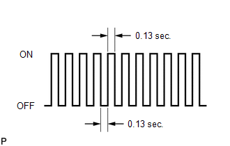
(f) Check that the MIL flashes as shown in the illustration.
(g) Start the engine. The MIL should turn off after the engine starts.
(h) Simulate the conditions of the malfunction described by the customer.
(i) Using the Techstream, check for DTCs and freeze frame data.
 Terminals Of Ecm
TERMINALS OF ECM
HINT:
The standard normal voltage between each pair of ECM terminals is shown in the
table below. The appropriate conditions for checking each pair of terminals are
also indic ...
 Data List / Active Test
DATA LIST / ACTIVE TEST
1. DATA LIST
NOTICE:
In the table below, the values listed under "Normal Condition" are reference
values. Do not depend solely on these reference values when dec ...
Other materials:
Data List / Active Test
DATA LIST / ACTIVE TEST
HINT:
By accessing the Data List displayed by the Techstream, you can check values
of switches and sensors without removing any parts. Reading the Data List as the
first step of troubleshooting is one method to shorten diagnostic time.
1. DATA LIST FOR OCCUPANT DETECTI ...
Engine does not Start but Initial Combustion Occurs
DESCRIPTION
If the key ID codes of the key and transponder key ECU assembly match, the engine
immobiliser system is unset and the engine start permission signal is sent to the
ECM. When the ID codes of the transponder key ECU assembly and ECM match, the engine
starts.
WIRING DIAGRAM
CAUTI ...
Personal Light Assembly
Components
COMPONENTS
ILLUSTRATION
Installation
INSTALLATION
PROCEDURE
1. INSTALL MAP LIGHT BULB
(a) Install the 2 map light bulbs to the 2 map light sockets.
(b) Turn the 2 map light sockets with 2 map light bulbs in the direction
indicated by the arrow shown in the ill ...
