Toyota Tacoma (2015-2018) Service Manual: Rear Door Black Out Tape
Components
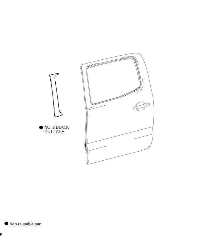
COMPONENTS
ILLUSTRATION
Installation
INSTALLATION
CAUTION / NOTICE / HINT
HINT:
- Use the same procedure for the RH and LH sides.
- The procedure described below is for the LH side.
PROCEDURE
1. REPAIR INSTRUCTION
.gif)
2. INSTALL NO. 2 BLACK OUT TAPE
(a) Refer to the illustration to position a new No. 2 black out tape.
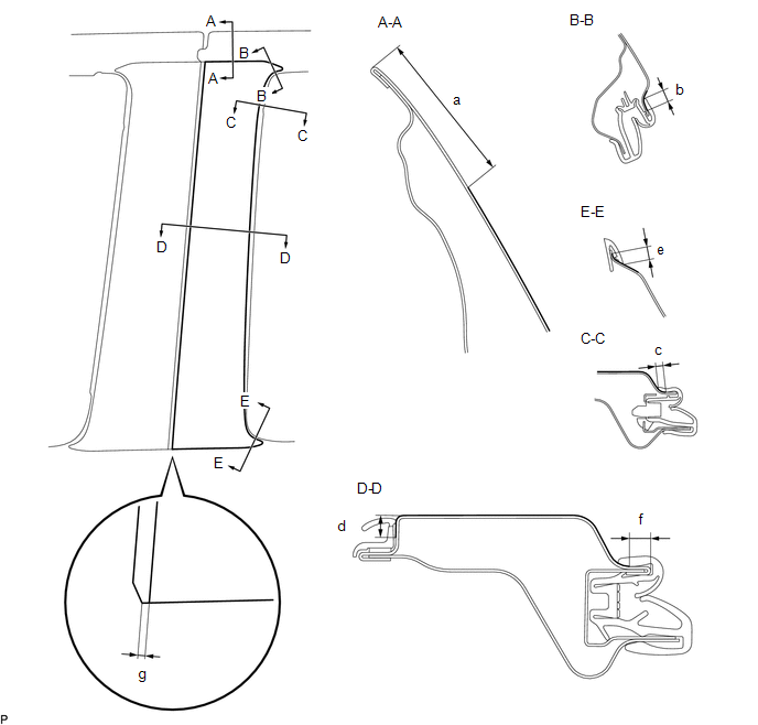 Standard Measurement
|
Dimension |
Measurement |
Dimension |
Measurement |
|---|---|---|---|
|
a |
41.8 mm (1.646 in.) |
b |
7.2 to 7.3 mm (0.283 to 0.2874 in.) |
|
c |
3.8 to 4.0 mm (0.150 to 0.157 in.) |
d |
6.0 to 6.2 mm (0.236 to 0.244 in.) 41.8 mm (** in.) |
|
e |
6.7 to 6.9 mm (0.264 to 0.272 in.) |
f |
5.7 to 5.9 mm (0.224 to 0.232 in.) |
|
g |
2.0 mm (0.0787 in.) |
- |
- |
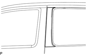
(b) Remove the release paper and apply the No. 2 black out tape.
3. INSTALL REAR DOOR GLASS OUTER WEATHERSTRIP ASSEMBLY
(See page
)
Removal
REMOVAL
CAUTION / NOTICE / HINT
HINT:
- Use the same procedure for the RH and LH sides.
- The procedure described below is for the LH side.
PROCEDURE
1. REMOVE REAR DOOR GLASS OUTER WEATHERSTRIP ASSEMBLY
(See page .gif) )
)
2. REMOVE NO. 2 BLACK OUT TAPE
(a) Using a heat light, heat the vehicle body and No. 2 black out tape.
Heating Temperature|
Item |
Temperature |
|---|---|
|
Vehicle Body and No. 2 Black Out Tape |
40 to 60°C (104 to 140°F) |
NOTICE:
Do not heat the vehicle body or No. 2 black out tape excessively.
|
(b) Pull back on one of the ends of the No. 2 black out tape to remove it. HINT: When pulling on the No. 2 black out tape, pull it parallel to the body. |
|
 Removal
REMOVAL
CAUTION / NOTICE / HINT
HINT:
Use the same procedure for the RH side and LH side.
The following procedure is for the LH side.
PROCEDURE
1. PRECAUTION
NOTICE:
After tur ...

Other materials:
Installation
INSTALLATION
PROCEDURE
1. ADJUST COMPRESSOR OIL
(a) for HFC-134a (R134a):
(1) When replacing the compressor and magnetic clutch with new ones, after gradually
discharging the refrigerant gas from the service valve, drain the following volume
of oil from new compressor and magnetic clutch bef ...
Destination Information Undefined (C1AB8)
DESCRIPTION
This DTC is stored when correct destination information is not sent from the
main body ECU (multiplex network body ECU) and destination information cannot be
confirmed after a blind spot monitor has been replaced.
DTC Code
DTC Detection Condition
Tr ...
Calibration
CALIBRATION
1. DESCRIPTION
(a) After replacing any VSC related components or performing wheel alignment
adjustment, clear and read the sensor calibration data.
Refer to the table below and then perform the necessary operation according to
the part to be replaced in order to perform calibratio ...
