Toyota Tacoma (2015-2018) Service Manual: Tail Gate Protector
Components
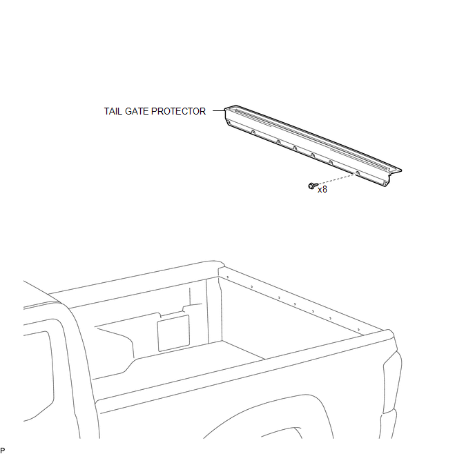
COMPONENTS
ILLUSTRATION
Removal
REMOVAL
PROCEDURE
1. REMOVE TAIL GATE PROTECTOR
|
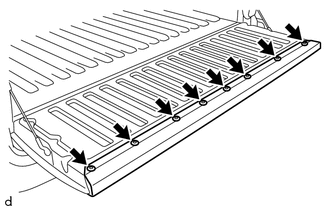
(a) Using a T30 "TORX" socket wrench, remove the 8 screws. |
|
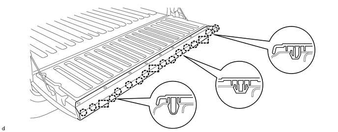
(b) Disengage the 14 claws and 3 guides to remove the tail gate protector.
Installation
INSTALLATION
PROCEDURE
1. INSTALL TAIL GATE PROTECTOR
(a) Engage the 3 guides and 14 claws to install the tail gate protector.
(b) Using a T30 "TORX" socket wrench, install the 8 screws.
 Side Moulding
Components
COMPONENTS
ILLUSTRATION
ILLUSTRATION
Removal
REMOVAL
CAUTION / NOTICE / HINT
HINT:
Use the same procedure for the RH side and LH side.
The following procedure is ...

Other materials:
Cruise Control Input Circuit (P0575)
DESCRIPTION
This DTC is stored when there is a malfunction in the ECM.
DTC No.
Detection Item
DTC Detection Condition
Trouble Area
P0575
Cruise Control Input Circuit
Either of the following conditions is met:
...
Sound Quality is Bad Only when CD is Played (Volume is Too Low)
PROCEDURE
1.
REPLACE CD AND RECHECK
(a) Replace the CD with a known good one and recheck.
(1) Check if the same malfunction occurs again.
OK:
Malfunction disappears.
OK
END
NG
REPLACE NAVIGATION RECEIVER ASSEMBLY ...
Open in Outer Mirror Indicator(Master) (C1AB4)
DESCRIPTION
This DTC is stored when the blind spot monitor sensor LH detects an open in the
blind spot monitor indicator LH.
DTC Code
DTC Detection Condition
Trouble Area
C1AB4
With the blind spot monitor main switch assembly (warning ...
