Toyota Tacoma (2015-2018) Service Manual: Removal
REMOVAL
PROCEDURE
1. REMOVE FRONT DOOR SCUFF PLATE LH (for Double Cab)
.gif)
2. REMOVE FRONT DOOR SCUFF PLATE LH (for Access Cab)
3. REMOVE COWL SIDE TRIM BOARD LH
4. REMOVE INSTRUMENT CLUSTER CENTER FINISH PANEL SUB-ASSEMBLY
5. REMOVE INSTRUMENT CLUSTER FINISH PANEL ASSEMBLY
6. REMOVE INSTRUMENT PANEL LOWER FINISH PANEL SUB-ASSEMBLY
7. REMOVE NAVIGATION RECEIVER ASSEMBLY WITH BRACKET (w/ Navigation System)
8. REMOVE RADIO AND DISPLAY RECEIVER ASSEMBLY WITH BRACKET (w/o Navigation System)
9. REMOVE HAZARD WARNING SIGNAL SWITCH ASSEMBLY (AIR CONDITIONING CONTROL ASSEMBLY) (for Automatic Air Conditioning System)
|
(a) Disengage the 8 clips to separate the hazard warning signal switch assembly (air conditioning control assembly). |
|
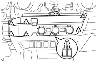
(b) Disconnect the connectors to remove the hazard warning signal switch assembly (air conditioning control assembly).
10. REMOVE HAZARD WARNING SIGNAL SWITCH ASSEMBLY (AIR CONDITIONING CONTROL ASSEMBLY) (for Manual Air Conditioning System)
|
(a) Disengage the 8 clips to separate the hazard warning signal switch assembly (air conditioning control assembly). |
|
(b) Disconnect the connectors to remove the hazard warning signal switch assembly (air conditioning control assembly).
 Components
COMPONENTS
ILLUSTRATION
ILLUSTRATION
...
 Inspection
INSPECTION
PROCEDURE
1. INSPECT HAZARD WARNING SIGNAL SWITCH ASSEMBLY (AIR CONDITIONING CONTROL ASSEMBLY)
(a) Check the resistance.
(1) Measure the resistance according to the value(s) ...
Other materials:
Front Camera Module Incorrect Axial Gap (C1AA8,C1AA9)
DESCRIPTION
If the forward recognition camera detects that the forward recognition camera
axis has deviated, DTC C1AA8 is stored. Also, if Forward Recognition Camera Axis
Adjustment is not performed after installing the forward recognition camera, DTC
C1AA9 is stored.
DTC No.
...
Vehicle Speed Sensor (C1A45)
DESCRIPTION
The blind spot monitor sensor receives vehicle speed signals from the skid control
ECU (brake actuator assembly) via CAN communication.
DTC Code
DTC Detection Condition
Trouble Area
C1A45
A fail flag is transmitted from the ...
Sleep Operation Failure of Occupant Classification ECU (B1796)
DESCRIPTION
During sleep mode, the occupant detection ECU monitors the condition of each
sensor while the ignition switch is off. In this mode, if the occupant detection
ECU detects an internal malfunction, DTC B1796 is set.
DTC No.
DTC Detections Conditions
Tr ...
