Toyota Tacoma (2015-2018) Service Manual: Side Moulding
Components
COMPONENTS
ILLUSTRATION
ILLUSTRATION
Removal
REMOVAL
CAUTION / NOTICE / HINT
HINT:
- Use the same procedure for the RH side and LH side.
- The following procedure is for the LH side.
- When removing the lower No. 2 side panel moulding, heat the vehicle body and lower No. 2 side panel moulding using a heat light.
|
Item |
Temperature |
|---|---|
|
Vehicle Body |
40 to 60°C (104 to 140°F) |
|
Lower No. 2 Side Panel Moulding |
20 to 30°C (68 to 86°F) |
NOTICE:
Do not heat the vehicle body or lower No. 2 side panel moulding excessively.
PROCEDURE
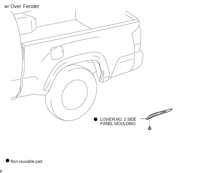
1. REMOVE LOWER NO. 2 SIDE PANEL MOULDING (w/ Over Fender)
(a) Using a heat light, heat the lower No. 2 side panel moulding.
|
(b) Remove the screw. Text in Illustration
|
|
(c) Disengage the 2 claws, and peel off the double-sided tape to remove the lower No. 2 side panel moulding.
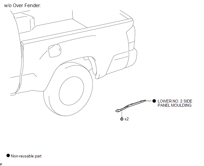
2. REMOVE LOWER NO. 2 SIDE PANEL MOULDING (w/o Over Fender)
(a) Using a heat light, heat the lower No. 2 side panel moulding.
|
(b) Remove the 2 screws. Text in Illustration
|
|
(c) Disengage the 2 claws, and peel off the double-sided tape to remove the lower No. 2 side panel moulding.
Installation
INSTALLATION
CAUTION / NOTICE / HINT
HINT:
- Use the same procedure for the RH side and LH side.
- The following procedure is for the LH side.
- When installing the lower No. 2 side panel moulding, heat the vehicle body and lower No. 2 side panel moulding using a heat light.
PROCEDURE
1. INSTALL LOWER NO. 2 SIDE PANEL MOULDING (w/ Over Fender)
(a) Clean the vehicle body surface.
(1) Using a heat light, heat the vehicle body surface.
(2) Remove the double-sided tape from the vehicle body.
(3) Clean off any tape adhesive residue with cleaner.
(b) Install a new lower No. 2 side panel moulding.
(1) Using a heat light, heat the vehicle body and a new lower No. 2 side panel moulding.
(2) Remove the release paper from the lower No. 2 side panel moulding.
HINT:
After removing the release paper, keep the exposed adhesive free from foreign matter.
|
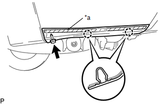
(3) Engage the claws to install the lower No. 2 side panel moulding. Text in Illustration
|
|
.png)
(4) Install the screw.
2. INSTALL LOWER NO. 2 SIDE PANEL MOULDING (w/o Over Fender)
(a) Clean the vehicle body surface.
(1) Using a heat light, heat the vehicle body surface.
(2) Remove the double-sided tape from the vehicle body.
(3) Clean off any tape adhesive residue with cleaner.
(b) Install a new lower No. 2 side panel moulding.
(1) Using a heat light, heat the vehicle body and a new lower No. 2 side panel moulding.
(2) Remove the release paper from the lower No. 2 side panel moulding.
HINT:
After removing the release paper, keep the exposed adhesive free from foreign matter.
|
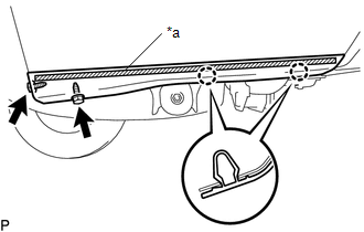
(3) Engage the claws to install the lower No. 2 side panel moulding. Text in Illustration
|
|
.png)
(4) Install the 2 screws.
 Installation
INSTALLATION
CAUTION / NOTICE / HINT
HINT:
Use the same procedures for the RH side and LH side.
The procedures listed below are for the LH side.
When installing a roof drip side mou ...
 Tail Gate Protector
Components
COMPONENTS
ILLUSTRATION
Removal
REMOVAL
PROCEDURE
1. REMOVE TAIL GATE PROTECTOR
(a) Using a T30 "TORX" socket wrench, remove the 8 screws.
...
Other materials:
USB Media Malfunction (B1585)
DESCRIPTION
This DTC is stored when a malfunction occurs in a connected device.
DTC No.
DTC Detection Condition
Trouble Area
B1585
USB Device Malfunction
Non mass-storage class or incompatible protocol USB device
...
Rear Shock Absorber
Components
COMPONENTS
ILLUSTRATION
Inspection
INSPECTION
PROCEDURE
1. INSPECT REAR SHOCK ABSORBER
(a) Compress and extend the shock absorber rod and check that there is no abnormal
resistance or abnormal sounds during operation.
If there is any abnormality, replace the shock absorb ...
System Description
SYSTEM DESCRIPTION
1. DESCRIPTION
The differential system (w/ Differential Lock) directly connects the
rear left and right wheels so that even if one wheel slips while driving
where drive torque transmission is difficult (such as on sand), the drive
torque of the other wheel is ...
