Toyota Tacoma (2015-2018) Service Manual: Speedometer Malfunction
DESCRIPTION
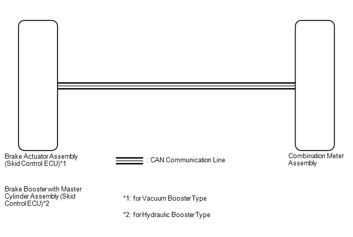
The meter CPU receives vehicle speed signals from the skid control ECU via the CAN communication system (CAN V1 Bus). The speed sensor detects the wheel speed and sends the appropriate signals to the skid control ECU. The skid control ECU supplies power to the vehicle speed sensor. The skid control ECU detects vehicle speed signals based on the pulses of the voltage.
HINT:
- Factors that affect the indicated vehicle speed include tire size, tire
inflation, and tire wear. The speed indicated on the speedometer has an
allowable margin of error. This can be tested using a speedometer tester
(calibrated chassis dynamometer). For details about testing and the margin
of error, see the reference chart (See page
.gif) ).
).
- If the vehicle speed sensor circuit has a malfunction, the skid control
ECU stores the DTCs. Troubleshoot the Brake Control System.
for Vacuum Booster type: (See page
)for Hydraulic Booster type: (See page
)
WIRING DIAGRAM
CAUTION / NOTICE / HINT
CAUTION:
If the vehicle speed is outside the allowable range when tested, perform the
on-vehicle inspection (See page
).
HINT:
Before starting the following inspection, check tire size and tire air pressure.
PROCEDURE
|
1. |
CHECK CAN COMMUNICATION SYSTEM |
(a) Check if a CAN communication DTC is output (See page
).
|
Result |
Proceed to |
|---|---|
|
CAN communication DTC is not output |
A |
|
CAN communication DTC is output |
B |
| B | .gif) |
GO TO CAN COMMUNICATION SYSTEM |
|
.gif)
|
2. |
PERFORM ACTIVE TEST USING TECHSTREAM (SPEED METER OPERATION) |
(a) Connect the Techstream to the DLC3.
(b) Turn the ignition switch to ON.
(c) Turn the Techstream on.
(d) Enter the following menus: Body Electrical / Combination Meter / Active Test.
(e) According to the display on the Techstream, perform the Active Test.
Combination Meter|
Tester Display |
Test Part |
Control Range |
Diagnostic Note |
|---|---|---|---|
|
Speed Meter Operation |
Speedometer |
|
Operate with IG ON and the vehicle is stopped. |
|
There is a deviation in the values displayed on the speedometer (Control range → Speedometer display) Reference mph*2:
Reference km/h*3:
|
- *1: for Speedometer with Imperial Units for Main Scale
- *2: for Speedometer with Metric Units for Main Scale
- *3: w/ Multi-information Display
OK:
Speedometer indication is normal.
| NG | |
REPLACE COMBINATION METER ASSEMBLY |
|
|
3. |
READ VALUE USING TECHSTREAM (VEHICLE SPEED METER) |
(a) Connect the Techstream to the DLC3.
(b) Turn the ignition switch to ON.
(c) Turn the Techstream on.
(d) Enter the following menus: Body Electrical / Combination Meter / Data List.
(e) According to the display on the Techstream, read the Data List.
Combination Meter|
Tester Display |
Measurement Item/Range |
Normal Condition |
Diagnostic Note |
|---|---|---|---|
|
Vehicle Speed Meter |
Vehicle speed/ Min.: 0 km/h (0 mph), Max.: 255 km/h (158 mph) |
Approximately same as actual vehicle speed (When vehicle is being driven) |
- |
OK:
Vehicle speed displayed on the Techstream is almost the same as the speedometer indication.
| NG | |
REPLACE COMBINATION METER ASSEMBLY |
|
|
4. |
CHECK VEHICLE STABILITY CONTROL SYSTEM |
(a) Check if a vehicle stability control DTC is output.
- for Vacuum Booster type: (See page
)
- for Hydraulic Booster type: (See page
)
|
Result |
Proceed to |
|---|---|
|
Vehicle stability control DTC is not output |
A |
|
Vehicle stability control (for Vacuum Booster type) DTC is output |
B |
|
Vehicle stability control (for Hydraulic Booster type) DTC is output |
C |
| A | |
REPLACE COMBINATION METER ASSEMBLY |
| B | |
GO TO VEHICLE STABILITY CONTROL SYSTEM (for Vacuum Booster type) |
| C | |
GO TO VEHICLE STABILITY CONTROL SYSTEM (for Hydraulic Booster type) |
 Entire Combination Meter does not Operate
DESCRIPTION
This circuit is the power source circuit for the meter. This circuit provides
two types of power sources, one is a constant power source mainly used as a backup
power source, and the ...
 Tachometer Malfunction
DESCRIPTION
In this circuit, the meter CPU receives engine speed signals from the ECM using
the CAN communication system (CAN V1 Bus). The meter CPU displays the engine speed
calculated based on ...
Other materials:
Problem Symptoms Table
PROBLEM SYMPTOMS TABLE
HINT:
Use the table below to help determine the cause of problem symptoms.
If multiple suspected areas are listed, the potential causes of the symptoms
are listed in order of probability in the "Suspected Area" column of the
table. Check each sy ...
Removal
REMOVAL
PROCEDURE
1. REMOVE INSTRUMENT PANEL LOWER FINISH PANEL SUB-ASSEMBLY
(See page )
2. REMOVE DRIVER SIDE JUNCTION BLOCK
(a) Disconnect the 5 connectors on the front side.
(b) Remove the 2 nuts to separate the driver side j ...
Inspection
INSPECTION
PROCEDURE
1. INSPECT BRAKE DRUM INSIDE DIAMETER
(a) Using a brake drum gauge or equivalent, measure the inside diameter of the
drum.
Standard inside diameter:
254 mm (10.00 in.)
Maximum inside diameter:
256 mm (10.08 in.)
If the inside diameter is greater than the maximum, r ...
