Toyota Tacoma (2015-2018) Service Manual: Removal
REMOVAL
PROCEDURE
1. REMOVE TRANSMISSION INSULATOR RH (for 2GR-FKS)
.gif)
2. REMOVE TRANSMISSION INSULATOR RH (for 2TR-FE)
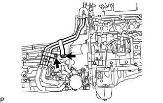
3. SEPARATE WATER BY-PASS PIPE (for 2GR-FKS)
|
(a) Remove the 2 bolts to separate the water by-pass pipe from the automatic transmission assembly. |
|
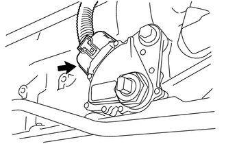
4. REMOVE PARK/NEUTRAL POSITION SWITCH
|
(a) Disconnect the park/neutral position switch connector. |
|
|
(b) Using a screwdriver, pry out the lock washer. |
|
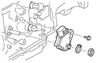
(c) Remove the nut and lock washer.
(d) Remove the bolt and park/neutral position switch from the automatic transmission assembly.
HINT:
Make sure that the manual valve lever shaft has not been rotated prior to installing the park/neutral position switch as the detent spring may become detached from the manual valve lever shaft.
 On-vehicle Inspection
ON-VEHICLE INSPECTION
PROCEDURE
1. INSPECT PARK/NEUTRAL POSITION SWITCH
(a) Apply the parking brake.
(b) Turn the ignition switch to ON.
(c) Depress the brake pedal and move the shift lever to an ...
 Adjustment
ADJUSTMENT
PROCEDURE
1. ADJUST PARK/NEUTRAL POSITION SWITCH
(a) While pushing the shift lock release button, move the shift lever to N.
(b) Remove the bolt of the park/neutral position switch.
(c ...
Other materials:
How To Proceed With Troubleshooting
CAUTION / NOTICE / HINT
HINT:
Use these procedures to troubleshoot the lane departure alert system.
*: Use the Techstream.
PROCEDURE
1.
VEHICLE BROUGHT TO WORKSHOP
NEXT
...
Diagnosis System
DIAGNOSIS SYSTEM
1. DESCRIPTION
When troubleshooting a vehicle with the diagnosis system, the only difference
from the usual troubleshooting procedure is connecting the Techstream to the vehicle
and reading various data output from the vehicle's skid control ECU (brake actuator
assembly) ...
Removal
REMOVAL
PROCEDURE
1. REMOVE INTAKE MANIFOLD
(See page )
2. REMOVE WIRE HARNESS CLAMP BRACKET
(a) Remove the 2 bolts and wire harness clamp bracket.
3. REMOVE FUEL TUBE SUB-ASSEMBLY
(a) Disconnect the fuel tube sub-assembly from ...
