Toyota Tacoma (2015-2018) Service Manual: System Diagram
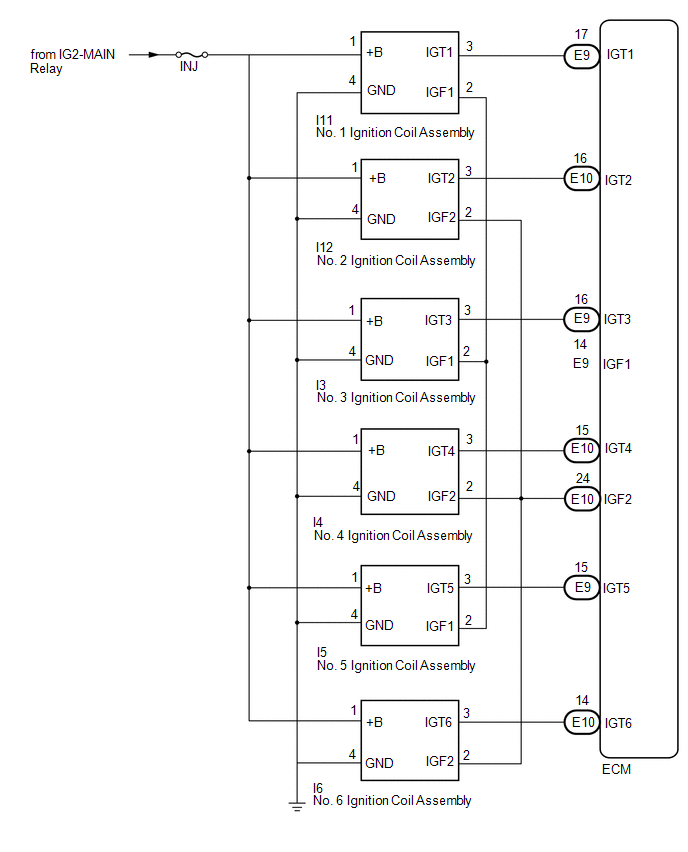
SYSTEM DIAGRAM
 Parts Location
PARTS LOCATION
ILLUSTRATION
ILLUSTRATION
ILLUSTRATION
...
 On-vehicle Inspection
ON-VEHICLE INSPECTION
CAUTION / NOTICE / HINT
HINT:
Perform "Inspection After Repair" after replacing an ignition coil assembly or
spark plug (See page ).
PROCEDURE
1. PERFORM SPARK ...
Other materials:
Adjustment
ADJUSTMENT
PROCEDURE
1. PREPARE VEHICLE FOR HEADLIGHT AIM ADJUSTMENT
(a) Prepare the vehicle:
Ensure that there is no damage or deformation to the body around the
headlights.
Fill the fuel tank.
Make sure that the oil is filled to the specified level.
Make sure that the co ...
Installation
INSTALLATION
PROCEDURE
1. INSPECT AND ADJUST BRAKE BOOSTER PUSH ROD
NOTICE:
The brake booster interior must not be a vacuum when adjusting the booster. Stop
the engine and depress the brake pedal several times until there is no vacuum in
the booster.
HINT:
Adjust the booster push rod when ...
On-vehicle Inspection
ON-VEHICLE INSPECTION
PROCEDURE
1. INSPECT REFRIGERANT PRESSURE
(a) This method uses a refrigerant recovery unit set to locate problem areas.
Read the refrigerant pressure when the test conditions are established.
Test conditions:
Temperature at the air inlet with the air recirculation ...
