Toyota Tacoma (2015-2018) Service Manual: System Diagram
SYSTEM DIAGRAM
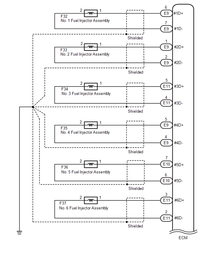
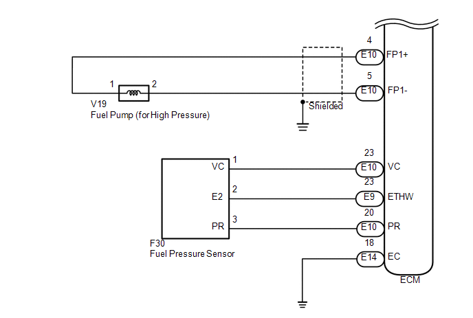
1. HIGH PRESSURE SIDE FUEL SYSTEM WIRING DIAGRAM
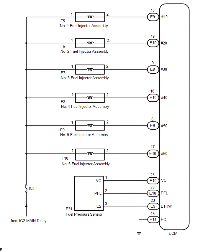
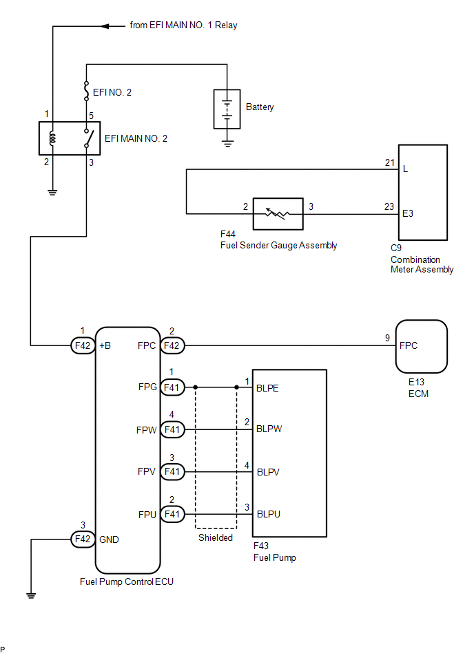
2. LOW PRESSURE SIDE FUEL SYSTEM WIRING DIAGRAM
 Parts Location
PARTS LOCATION
ILLUSTRATION
ILLUSTRATION
ILLUSTRATION
...
 On-vehicle Inspection
ON-VEHICLE INSPECTION
PROCEDURE
1. CHECK FUEL PUMP OPERATION AND INSPECT FOR FUEL LEAK
(a) Connect the Techstream to the DLC3.
(1) Turn the ignition switch to ON.
NOTICE:
Do not start the engine ...
Other materials:
Definition Of Terms
DEFINITION OF TERMS
Term
Definition
Monitor Description
Description of what the ECM monitors and how it detects malfunctions
(monitoring purpose and details).
Related DTCs
A group of diagnostic trouble codes that are ...
Rear Leaf Spring
Components
COMPONENTS
ILLUSTRATION
Disassembly
DISASSEMBLY
PROCEDURE
1. REMOVE BUSH
(a) Fix the spring in a vise.
(b) Using a hack saw, cut both ends off the bushes.
(c) Using SST and a press, press out the 2 bushes.
SST: 09950-60010
09951-00350
SST: 09950-70010
...
Voice Recognition Microphone Disconnected (B1579)
DESCRIPTION
The radio and display receiver assembly and telephone microphone assembly are
connected to each other using the microphone connection detection signal lines.
This DTC is stored when a microphone connection detection signal line is disconnected.
DTC Code
DTC Det ...
