Toyota Tacoma (2015-2018) Service Manual: System Diagram
SYSTEM DIAGRAM
 Communication Table
|
Transmitting ECU (Transmitter) |
Receiving ECU (Receiver) |
Signal |
Line |
|---|---|---|---|
|
Main body ECU (Multiplex Network Body ECU) |
Combination Meter Assembly |
Wireless door lock hazard warning light request signal |
CAN |
 System Description
SYSTEM DESCRIPTION
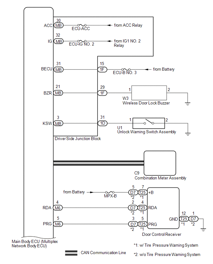
1. WIRELESS DOOR LOCK CONTROL SYSTEM
The wireless door lock control system functions to lock and unlock all the doors
from a distance. The system is controlled by a door control ...
 How To Proceed With Troubleshooting
CAUTION / NOTICE / HINT
HINT:
The wireless door lock control system troubleshooting procedures are
based on the premise that the power door lock control system is operating
normally. ...
Other materials:
Speaker Output Short (B15C3)
DESCRIPTION
This DTC is stored when a malfunction occurs in the speakers.
DTC No.
DTC Detection Condition
Trouble Area
B15C3
A short is detected in the speaker output circuit.
Harness or connector
Speaker
...
Side doors
The vehicle can be locked/unlocked using the wireless remote control, key or
door lock switch.
■ Wireless remote control (if equipped)
■ Key
Regular Cab models
Locks the door
Unlocks the door
Access Cab and Double Cab models
Locks all doors
Unlocks all doors
Turning ...
Installation
INSTALLATION
PROCEDURE
1. INSTALL FRONT DIFFERENTIAL CARRIER ASSEMBLY
(a) Connect the actuator hose and connector.
(b) Install the No. 1 mounting support with the 3 bolts.
Torque:
186 N·m {1899 kgf·cm, 138 ft·lbf}
(c) Install the No. 2 mounting support with the 2 bolts.
Torque:
160 N ...
