Toyota Tacoma (2015-2018) Service Manual: System Diagram
SYSTEM DIAGRAM
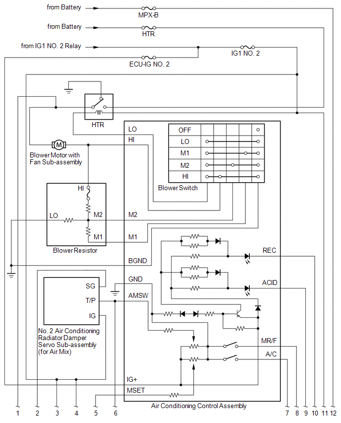
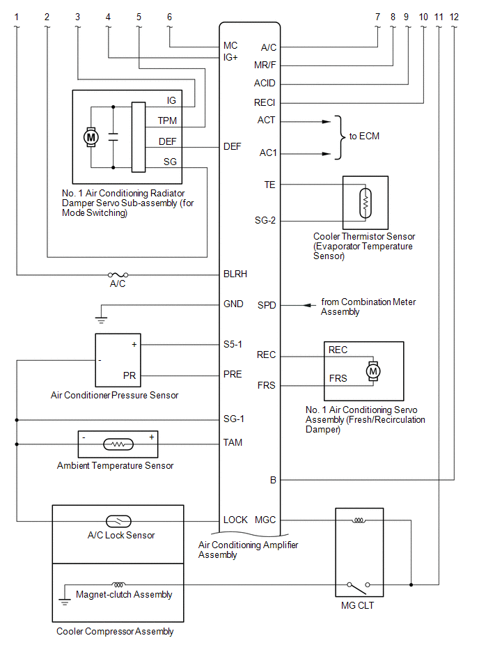
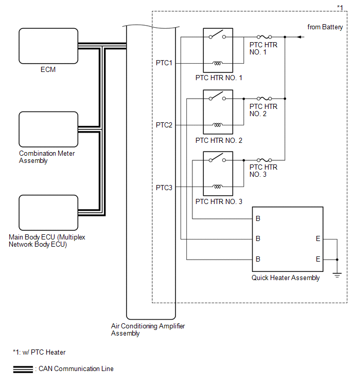
 System Description
SYSTEM DESCRIPTION
1. GENERAL
(a) The air conditioning system has the following controls.
Control
Outline
Manual Control
The air conditioner amplif ...
 Problem Symptoms Table
PROBLEM SYMPTOMS TABLE
HINT:
Use the table below to help determine the cause of problem symptoms.
If multiple suspected areas are listed, the potential causes of the symptoms
are lis ...
Other materials:
Position Initialization Incomplete (B2343)
DESCRIPTION
This DTC is stored when the sliding roof ECU (sliding roof drive gear sub-assembly)
has not been initialized.
DTC No.
DTC Detection Condition
Trouble Area
B2343
Sliding roof ECU (sliding roof drive gear sub-assembly) has no ...
Neutral Position Switch Circuit
DESCRIPTION
The ECM uses the neutral position switch installed to the manual transmission
assembly to detect when the transmission is in the neutral position.
WIRING DIAGRAM
PROCEDURE
1.
READ VALUE USING TECHSTREAM (NEUTRAL SWITCH)
(a) Connect the Techstream ...
Problem Symptoms Table
PROBLEM SYMPTOMS TABLE
NOTICE:
After replacing the stereo component tuner assembly of vehicles subscribed
to pay-type satellite radio broadcasts, XM radio ID registration is necessary
(w/ SDARS System).
HINT:
Use the table below to help determine the cause of proble ...
