Toyota Tacoma (2015-2018) Service Manual: Parts Location
PARTS LOCATION
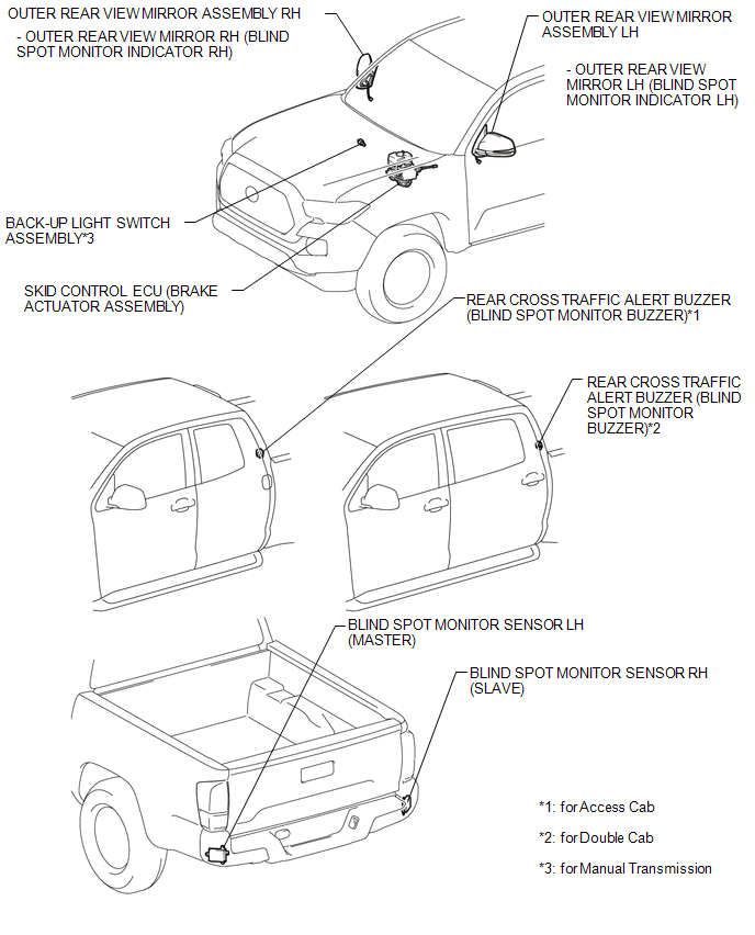
ILLUSTRATION
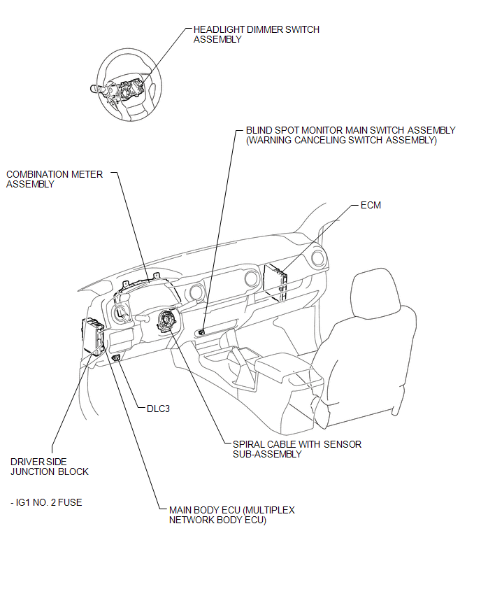
ILLUSTRATION
 Precaution
PRECAUTION
1. IGNITION SWITCH EXPRESSIONS
(a) The type of ignition switch used on this model differs according to the specifications
of the vehicle. The expressions listed in the table below are u ...
 System Description
SYSTEM DESCRIPTION
1. GENERAL
(a) The blind spot monitor system has the blind spot monitor function and rear
cross traffic alert function.
(1) Blind spot monitor function
The blind spot m ...
Other materials:
Problem Symptoms Table
PROBLEM SYMPTOMS TABLE
HINT:
Use the table below to help determine the cause of problem symptoms.
If multiple suspected areas are listed, the potential causes of the symptoms
are listed in order of probability in the "Suspected Area" column of the
table. Check each sy ...
Invalid Data Received from Deceleration Sensor (C1442,C1443)
DESCRIPTION
The airbag sensor assembly has a built-in yaw rate and acceleration sensor.
The skid control ECU (brake actuator assembly) receives signals from the yaw
rate and acceleration sensor (airbag sensor assembly) via the CAN communication
system.
DTC No.
Detection ...
Voice Guidance does not Function
PROCEDURE
1.
CHECK VOICE GUIDANCE SETTING
(a) Check that the voice guidance setting is not off.
OK:
Voice guidance setting is not off.
NG
CHANGE THE VOICE GUIDANCE SETTING TO ON
OK
...
