Toyota Tacoma (2015-2018) Service Manual: System Description
SYSTEM DESCRIPTION
1. ENGINE IMMOBILISER SYSTEM DESCRIPTION
The engine immobiliser system is designed to prevent the vehicle from being stolen. This system uses the transponder key ECU assembly that stores the key ID codes of authorized ignition keys. If an attempt is made to start the engine using an unauthorized key, the transponder key ECU assembly sends a signal to the ECM to prohibit fuel delivery and ignition, effectively disabling the engine.
2. FUNCTION OF MAIN COMPONENTS
|
Component |
Outline |
|---|---|
|
Transponder key ECU assembly |
|
|
Transponder key coil |
When a key is inserted into the ignition key cylinder, the transponder key amplifier receives the key ID code from the transponder chip in the key grip and outputs it to the transponder key ECU assembly. |
|
ECM |
The ECM receives key ID code verification results from the transponder key ECU assembly. The ECM also verifies the ECUs. Then judgment of whether to immobilise the engine is made. |
|
Unlock warning switch assembly |
The unlock warning switch assembly detects if the key is in the ignition key cylinder and outputs the result to the transponder key ECU assembly. |
|
Security indicator light (air conditioning control assembly) |
Depending on the operation of the transponder key ECU assembly, the security indicator light comes on or starts blinking. |
3. SYSTEM FUNCTION
(a) When the transponder key ECU assembly detects that the unlock warning switch assembly is on, the transponder key ECU assembly applies current to the transponder key coil and produces a magnetic field around the antenna coil. A transponder chip in the key grip outputs a key ID code signal using electromotive force generated by the magnetic field. The transponder key coil receives the signal and sends it to the transponder key ECU assembly. The transponder key ECU assembly checks if the key ID code received from the transponder key coil matches the registered key ID code.
When the engine is started, the ECM communicates with the transponder key ECU assembly and checks the key verification result. In addition, the ECM checks if the engine ID codes stored in the transponder key ECU assembly and ECM match. If they do not match, the ECM prohibits engine start.
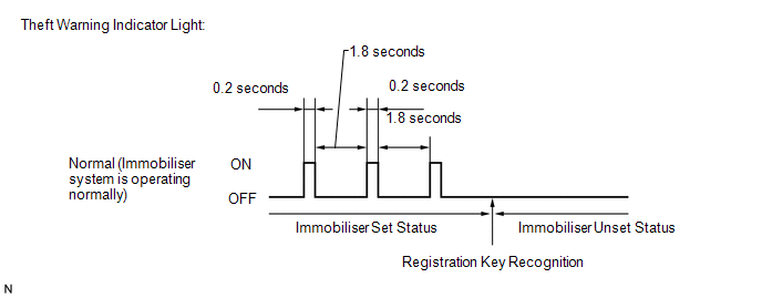
(b) The security indicator light blinking pattern is as shown below (when changing from the immobiliser set status to the unset status):
 Precaution
PRECAUTION
1. PRECAUTIONS WHEN USING TECHSTREAM
(a) When using the Techstream to troubleshoot the engine immobiliser system:
Connect the Techstream to the DLC3 while the ignition switch is off, and ...
 System Diagram
SYSTEM DIAGRAM
...
Other materials:
Open in Driver Side Electrical Antenna Circuit (B27A1)
DESCRIPTION
The certification ECU (smart key ECU assembly) generates a request signal and
transmits the signal to the front door outside handle assembly LH [electrical key
antenna] at intervals of 0.25 seconds. For the front door outside handle assembly
LH [electrical key antenna] to detect w ...
Freeze Frame Data
FREEZE FRAME DATA
1. FREEZE FRAME DATA
(a) Using the Techstream, check the vehicle condition (ECU, sensor) when the
brake system operates or a DTC is output.
2. CHECK FREEZE FRAME DATA WHEN BRAKE SYSTEM OPERATES
(a) Freeze frame data is stored when the brake system operates. The freeze frame
...
Glass Position Initialization Incomplete (B2313)
DESCRIPTION
The power window regulator motor assembly is operated by the power window regulator
master switch assembly or power window regulator switch assembly. The power window
regulator motor assembly has motor, regulator and ECU functions.
When the ECU determines that the power window regu ...
