Toyota Tacoma (2015-2018) Service Manual: Parts Location
PARTS LOCATION
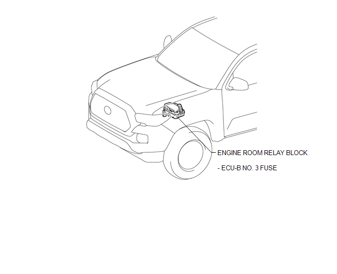
ILLUSTRATION
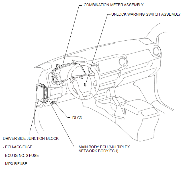
ILLUSTRATION
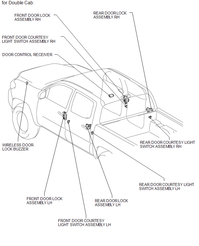
ILLUSTRATION
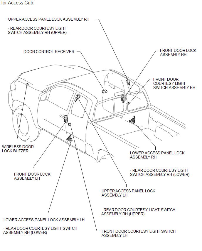
ILLUSTRATION
 Precaution
PRECAUTION
1. DOOR CONTROL RECEIVER EXPRESSIONS
(a) The type of door control receiver used on this model differs according to
the specifications of the vehicle. The expressions listed in the table ...
 System Description
SYSTEM DESCRIPTION
1. WIRELESS DOOR LOCK CONTROL SYSTEM
The wireless door lock control system functions to lock and unlock all the doors
from a distance. The system is controlled by a door control ...
Other materials:
Installation
INSTALLATION
PROCEDURE
1. INSPECT AND ADJUST BRAKE BOOSTER PUSH ROD
NOTICE:
The brake booster interior must not be a vacuum when adjusting the booster. Stop
the engine and depress the brake pedal several times until there is no vacuum in
the booster.
HINT:
Adjust the booster push rod when ...
Dtc Combination Table
DTC COMBINATION TABLE
HOW TO INTERPRET COMMUNICATION DTCS (DTCS THAT START WITH U)
(a) If a CAN communication error cannot be reproduced, determine the suspected
malfunctioning part using the DTCs stored in ECUs that are connected to the CAN
buses by following the procedure below.
HINT:
Comm ...
Terminals Of Ecu
TERMINALS OF ECU
1. CHECK 4 WHEEL DRIVE CONTROL ECU
Text in Illustration
*a
Component with harness connected
(4 Wheel Drive Control ECU)
-
-
(a) Measure the resistance and voltage according to the value(s) in the table
below.
...
