Toyota Tacoma (2015-2018) Service Manual: Steering Pad Switch
Components
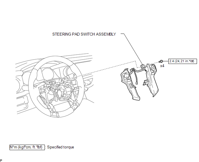
COMPONENTS
ILLUSTRATION
Removal
REMOVAL
PROCEDURE
1. REMOVE STEERING PAD
(See page .gif) )
)
2. REMOVE STEERING PAD SWITCH ASSEMBLY
|
(a) Disconnect the 2 connectors. |
|
.png)
(b) Disengage the 2 clamps.
(c) Remove the 4 screws.
|
(d) Disengage the 6 guides and 2 claws to remove the steering pad switch assembly. NOTICE: Disengage the 2 guides on the upper part of the steering pad switch assembly first. |
|
.png)
Inspection
INSPECTION
PROCEDURE
1. INSPECT STEERING PAD SWITCH ASSEMBLY
(See page .gif) )
)
Installation
INSTALLATION
PROCEDURE
1. INSTALL STEERING PAD SWITCH ASSEMBLY
(a) Engage the 6 guides and 2 claws to install the steering pad switch assembly.
(b) Install the 4 screws.
Torque:
2.4 N·m {24 kgf·cm, 21 in·lbf}
(c) Engage the 2 clamps.
(d) Connect the 2 connectors.
2. INSTALL STEERING PAD
(See page .gif) )
)
 Speed Signal Circuit
DESCRIPTION
The combination meter assembly receives the vehicle speed signal from this circuit.
The wheel speed sensors produce an output that varies according to the vehicle speed.
The wheel spe ...
 Mirror
...
Other materials:
Check For Intermittent Problems
CHECK FOR INTERMITTENT PROBLEMS
1. DESCRIPTION
HINT:
A momentary interruption (open circuit) in the connectors and/or wire harness
between the sensors and ECUs can be detected through the ECU data monitor function
of the Techstream.
(a) Turn the ignition switch off.
(b) Connect the Techstre ...
VSC OFF Switch Circuit
DESCRIPTION
The skid control ECU assembly is connected to the combination meter assembly
via CAN communication.
Pressing the VSC OFF switch turns off TRAC operation, and pressing and holding
this switch turns off TRAC and VSC operation.
If TRAC and VSC operations are turned off, the TRAC OFF ...
Installation
INSTALLATION
CAUTION / NOTICE / HINT
HINT:
Use the same procedure for both the RH and LH sides.
The procedure described below is for the LH side.
PROCEDURE
1. INSTALL CURTAIN SHIELD AIRBAG ASSEMBLY
(a) Insert the 5 hooks, install 6 new bolts, 2 new clips with pins and 2 new
...
