Toyota Tacoma (2005–2015) Owners Manual: Gauges and meters
The following gauges, meters and displays illuminate when the engine switch is in the ON position.
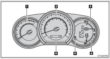
 Tachometer
Displays the engine speed in revolutions per minute.
 Speedometer
Displays the vehicle speed.
 Engine coolant temperature gauge
Displays the engine coolant temperature.
 Fuel gauge
Displays the quantity of fuel remaining in the tank.
 ODO/TRIP button
Switches between odometer and trip meter displays. Pushing and holding the button will reset the trip meter when the trip meter is being displayed.
 Odometer/trip meter
Odometer: Displays the total distance the vehicle has been driven.
Trip meter: Displays the distance the vehicle has been driven since the meter was last reset. Trip meters A and B can be used to record and display different distances independently.
Odometer and trip meter display button
Pressing this button switches between odometer and trip meter displays.
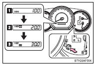
 Odometer
 Trip meter A*
 Trip meter B*
*: Pushing and holding the button will reset the trip meter.
Instrument panel light control
The brightness of the instrument panel lights can be adjusted.
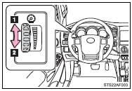
 Brighter
 Darker
NOTICE
■To prevent damage to the engine and its components
●Do not let the indicator needle of the tachometer enter the red zone, which indicates the maximum engine speed.
●The engine may be overheating if the engine coolant temperature gauge is in the red zone (H). In this case, immediately stop the vehicle in a safe place, and check the engine after it has cooled completely.

 Indicators and warning lights
The indicator and warning lights on the instrument cluster and center panel
inform the driver of the status of the vehicle’s various systems.
Instrument cluster
Center panel
■ Indic ...
Other materials:
What to do if...
■ Instrument cluster
■ Center panel
■Warning lights
*1: Slip indicator comes on.
*2: The indicator flashes to indicate a malfunction.
GAS STATION INFORMATION
...
Reassembly
REASSEMBLY
PROCEDURE
1. INSTALL BRAKE BOOSTER ACCUMULATOR ASSEMBLY
(a) Place the brake booster pump in a vise with a cloth.
(b) Install the brake booster accumulator pipe, compression spring and a new
O-ring.
NOTICE:
Ensure that no foreign matter enters the pump.
(c) Using a socket wrench ...
A/C ECU Vehicle Information Reading/Writing Processor Malfunction (B15F5)
DESCRIPTION
This DTC is stored when items controlled by the Air conditioning amplifier assembly
cannot be customized via the navigation system vehicle customization screen.
HINT:
The Air conditioning amplifier assembly controls the air conditioning system
related items that are customizable v ...
