Toyota Tacoma (2015-2018) Service Manual: Sound Signal Circuit between Radio Receiver and Stereo Jack Adapter
DESCRIPTION
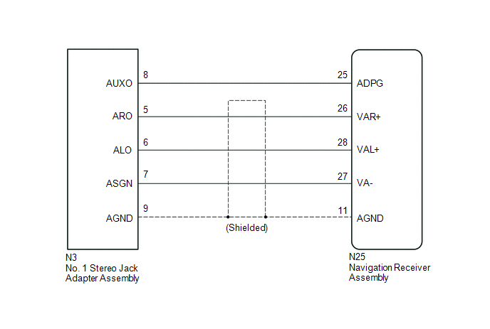
The No. 1 stereo jack adapter assembly sends the sound signal from an external device to the navigation receiver assembly via this circuit.
If there is an open or short in the circuit, sound cannot be heard from the speakers even if there is no malfunction in the stereo component amplifier assembly, navigation receiver assembly or speakers.
WIRING DIAGRAM
PROCEDURE
|
1. |
CHECK HARNESS AND CONNECTOR (NAVIGATION RECEIVER ASSEMBLY - NO. 1 STEREO JACK ADAPTER ASSEMBLY) |
(a) Disconnect the N25 navigation receiver assembly connector.
(b) Disconnect the N3 No. 1 stereo jack adapter assembly connector.
(c) Measure the resistance according to the value(s) in the table below.
Standard Resistance:
|
Tester Connection |
Condition |
Specified Condition |
|---|---|---|
|
N25-25 (ADPG) - N3-8 (AUXO) |
Always |
Below 1 Ω |
|
N25-26 (VAR+) - N3-5 (ARO) |
Always |
Below 1 Ω |
|
N25-28 (VAL+) - N3-6 (ALO) |
Always |
Below 1 Ω |
|
N25-27 (VA-) - N3-7 (ASGN) |
Always |
Below 1 Ω |
|
N25-11 (AGND) - N3-9 (AGND) |
Always |
Below 1 Ω |
|
N25-25 (ADPG) - Body ground |
Always |
10 kΩ or higher |
|
N25-26 (VAR+) - Body ground |
Always |
10 kΩ or higher |
|
N25-28 (VAL+) - Body ground |
Always |
10 kΩ or higher |
|
N25-27 (VA-) - Body ground |
Always |
10 kΩ or higher |
|
N25-11 (AGND) - Body ground |
Always |
10 kΩ or higher |
| OK | .gif) |
PROCEED TO NEXT SUSPECTED AREA SHOWN IN PROBLEM SYMPTOMS TABLE |
| NG | |
REPAIR OR REPLACE HARNESS OR CONNECTOR |
 Data Signal Circuit between Stereo Jack Adapter and Extension Module
DESCRIPTION
The No. 1 stereo jack adapter assembly sends the sound data signal or image data
signal from a USB device to the navigation receiver assembly via this circuit.
WIRING DIAGRAM
PROCED ...
 Data Signal Circuit between Navigation Receiver Assembly and Extension Module
DESCRIPTION
The stereo component tuner assembly sends the sound data signal or image data
signal from a device to the navigation receiver assembly via this circuit.
WIRING DIAGRAM
CAUTION / NOT ...
Other materials:
Installation
INSTALLATION
PROCEDURE
1. SET NO. 1 CYLINDER TO TDC/COMPRESSION
2. INSTALL CAMSHAFT TIMING GEAR BOLT
NOTICE:
There are different types of camshaft timing gear bolts. Make sure to check the
identification mark to determine the tightening torque.
*a
Identification Ma ...
On-vehicle Inspection
ON-VEHICLE INSPECTION
PROCEDURE
1. INSPECT DRIVE BELT
(a) Visually check the belt for defects, such as excessive wear and frayed cords.
If any defects are found, replace the drive belt.
HINT:
Replace the belt if there are any missing ribs.
2. BLEED POWER STEERING SYSTEM
(a) Check the fluid ...
Open or Short in Rear Speed Sensor RH Circuit (C1407,C1408)
DESCRIPTION
Refer to DTCs C1403 and C1404 (See page ).
DTC No.
Detection Item
DTC Detection Condition
Trouble Area
C1407
Open or Short in Rear Speed Sensor RH Circuit
Either of the following is detected:
...
