Toyota Tacoma (2015-2018) Service Manual: Data Signal Circuit between Stereo Jack Adapter and Extension Module
DESCRIPTION
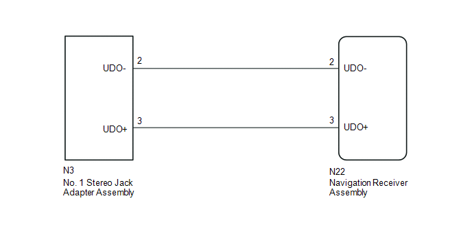
The No. 1 stereo jack adapter assembly sends the sound data signal or image data signal from a USB device to the navigation receiver assembly via this circuit.
WIRING DIAGRAM
PROCEDURE
|
1. |
CHECK HARNESS AND CONNECTOR (NAVIGATION RECEIVER ASSEMBLY - NO. 1 STEREO JACK ADAPTER ASSEMBLY) |
(a) Disconnect the N22 navigation receiver assembly connector.
(b) Disconnect the N3 No. 1 stereo jack adapter assembly connector.
(c) Measure the resistance according to the value(s) in the table below.
Standard Resistance:
|
Tester Connection |
Condition |
Specified Condition |
|---|---|---|
|
N3-2 (UDO-) - N22-2 (UDO-) |
Always |
Below 1 Ω |
|
N3-3 (UDO+) - N22-3 (UDO+) |
Always |
Below 1 Ω |
|
N3-2 (UDO-) - Body ground |
Always |
10 kΩ or higher |
|
N3-3 (UDO+) - Body ground |
Always |
10 kΩ or higher |
| OK | .gif) |
PROCEED TO NEXT SUSPECTED AREA SHOWN IN PROBLEM SYMPTOMS TABLE |
| NG | |
REPAIR OR REPLACE HARNESS OR CONNECTOR |
 Sound Signal Circuit between Radio Receiver and Stereo Component Amplifier
DESCRIPTION
The navigation receiver assembly sends a sound signal to the stereo component
amplifier assembly via this circuit.
The sound signal that has been sent is amplified by the stereo compon ...
 Sound Signal Circuit between Radio Receiver and Stereo Jack Adapter
DESCRIPTION
The No. 1 stereo jack adapter assembly sends the sound signal from an external
device to the navigation receiver assembly via this circuit.
If there is an open or short in the circuit, ...
Other materials:
If the shift lever cannot be shifted from P (vehicles with an automatic transmission)
If the shift lever cannot be shifted with your foot on the brake, there may
be a problem with the shift lock system (a system to prevent accidental operation
of the shift lever). Have the vehicle inspected by your Toyota dealer immediately.
The following steps may be used as an emergency measur ...
Invalid Data Received from Vehicle Dynamics Control Module (U0416)
DESCRIPTION
This DTC is detected if a wheel speed malfunction signal is sent from the skid
control ECU (brake actuator assembly).
DTC No.
Detection Item
DTC Detection Condition
Trouble Area
U0416
Invalid Data Received From V ...
Check Bus 5 Line for Short to +B
DESCRIPTION
There may be a short circuit between one of the CAN bus lines and +B when no
resistance exists between terminal 15 (CA5H) of the central gateway ECU (network
gateway ECU) and terminal 16 (BAT) of the DLC3, or terminal 16 (CA5L) of the central
gateway ECU (network gateway ECU) and ...
