Toyota Tacoma (2015-2018) Service Manual: Sensor (Motor) Failure (B2341,B2344)
DESCRIPTION
When the sliding roof ECU (sliding roof drive gear sub-assembly) detects a motor malfunction and the sliding roof operation is stopped, DTC B2341 is stored.
When the sliding roof ECU (sliding roof drive gear sub-assembly) detects a gear position malfunction and the sliding roof operation is stopped, DTC B2344 is stored.
|
DTC No. |
DTC Detection Condition |
Trouble Area |
|---|---|---|
|
B2341 |
Sensor (motor) failure (When the sliding roof ECU enters fail-safe mode due to a problem with the motor) |
|
|
B2344 |
Position failure (When the sliding roof ECU enters fail-safe mode due to a problem with the gear position) |
|
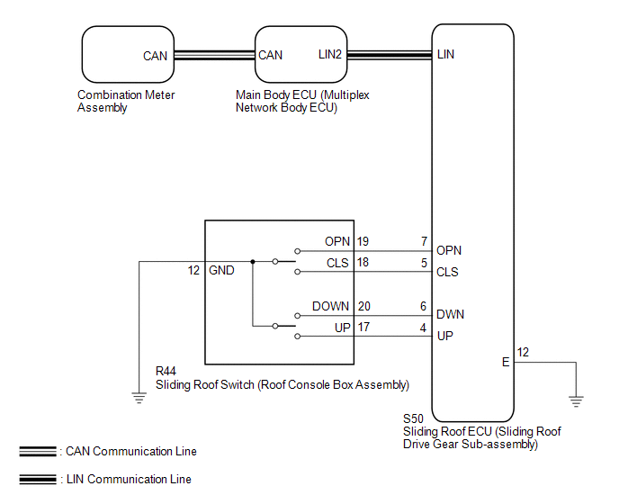
WIRING DIAGRAM
CAUTION / NOTICE / HINT
NOTICE:
- When the sliding roof ECU (sliding roof drive gear sub-assembly) is
removed and reinstalled or replaced, it requires initialization (See page
.gif) ).
). - The sliding roof system uses the CAN and LIN communication systems.
First, confirm that there are no malfunctions in the CAN and LIN communication
systems. Refer to the How to Proceed with Troubleshooting procedure (See
page ).
PROCEDURE
|
1. |
CHECK SLIDING ROOF OPERATION |
(a) Check the sliding roof auto operation (See page
).
OK:
Auto operation operates normally.
| NG | .gif) |
GO TO STEP 3 |
|
.gif)
|
2. |
CHECK DTC OUTPUT |
(a) Clear the DTCs (See page ).
(b) Check for DTCs.
OK:
DTC B2341 or B2344 is not output.
| OK | |
USE SIMULATION METHOD TO CHECK |
| NG | |
REPLACE SLIDING ROOF ECU (SLIDING ROOF DRIVE GEAR SUB-ASSEMBLY) |
|
3. |
INITIALIZE SLIDING ROOF ECU (SLIDING ROOF HOUSING SUB-ASSEMBLY) |
(a) Check that the sliding roof ECU (sliding roof drive gear sub-assembly) can
be initialized (See page ).
OK:
Sliding roof ECU (sliding roof drive gear sub-assembly) can be initialized.
| NG | |
GO TO STEP 5 |
|
|
4. |
CHECK DTC OUTPUT |
(a) Clear the DTCs (See page ).
(b) Check for DTCs.
OK:
DTC B2341 or B2344 is not output.
| OK | |
END (PROBLEM DUE TO INITIALIZATION FAILURE) |
| NG | |
REPLACE SLIDING ROOF ECU (SLIDING ROOF DRIVE GEAR SUB-ASSEMBLY) |
|
5. |
CHECK HARNESS AND CONNECTOR (SLIDING ROOF ECU - SLIDING ROOF SWITCH AND BODY GROUND) |
(a) Disconnect the R44 sliding roof switch (roof console box assembly) connector.
(b) Disconnect the S50 sliding roof ECU (sliding roof drive gear sub-assembly) connector.
(c) Measure the resistance according to the value(s) in the table below.
Standard Resistance:
|
Tester Connection |
Condition |
Specified Condition |
|---|---|---|
|
S50-5 (CLS) - R44-18 (CLS) |
Always |
Below 1 Ω |
|
S50-5 (CLS) - Body ground |
Always |
10 kΩ or higher |
|
S50-7 (OPN) - R44-19 (OPN) |
Always |
Below 1 Ω |
|
S50-7 (OPN) - Body ground |
Always |
10 kΩ or higher |
|
S50-6 (DWN) - R44-20 (DOWN) |
Always |
Below 1 Ω |
|
S50-6 (DWN) - Body ground |
Always |
10 kΩ or higher |
|
S50-4 (UP) - R44-17 (UP) |
Always |
Below 1 Ω |
|
S50-4 (UP) - Body ground |
Always |
10 kΩ or higher |
|
R44-12 (GND) - Body ground |
Always |
Below 1 Ω |
|
S50-12 (E) - Body ground |
Always |
Below 1 Ω |
| NG | |
REPAIR OR REPLACE HARNESS OR CONNECTOR |
|
|
6. |
INSPECT SLIDING ROOF SWITCH (ROOF CONSOLE BOX ASSEMBLY) |
|
(a) Remove the sliding roof switch (roof console box assembly) (See page
|
|
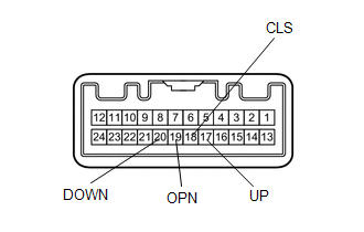
(b) Measure the resistance according to the value(s) in the table below.
Standard Resistance:
|
Tester Connection |
Condition |
Specified Condition |
|---|---|---|
|
17 (UP) - 12 (GND) |
UP switch is pressed |
Below 1 Ω |
|
17 (UP) - 12 (GND) |
UP switch is not pressed |
10 kΩ or higher |
|
20 (DOWN) - 12 (GND) |
DOWN switch is pressed |
Below 1 Ω |
|
20 (DOWN) - 12 (GND) |
DOWN switch is not pressed |
10 kΩ or higher |
|
19 (OPN) - 12 (GND) |
OPEN switch is pressed |
Below 1 Ω |
|
19 (OPN) - 12 (GND) |
OPEN switch is not pressed |
10 kΩ or higher |
|
18 (CLS) - 12 (GND) |
CLOSE switch is pressed |
Below 1 Ω |
|
18 (CLS) - 12 (GND) |
CLOSE switch is not pressed |
10 kΩ or higher |
|
*a |
Component without harness connected (Sliding Roof Switch (Roof Console Box Assembly)) |
| OK | |
REPLACE SLIDING ROOF ECU (SLIDING ROOF DRIVE GEAR SUB-ASSEMBLY) |
| NG | |
REPLACE SLIDING ROOF SWITCH (ROOF CONSOLE BOX ASSEMBLY) |
 Diagnostic Trouble Code Chart
DIAGNOSTIC TROUBLE CODE CHART
Sliding Roof (Sliding Roof ECU (Sliding Roof Drive Gear Sub-assembly))
DTC Code
Detection Item
See page
B2341
...
 Remote Control System does not Operate
DESCRIPTION
The main body ECU (multiplex network body ECU) receives remote control signals
from the driver door key cylinder or wireless transmitter. Then, the main body ECU
(multiplex network bo ...
Other materials:
Indicator Circuit
DESCRIPTION
The forward recognition camera sends indicator illumination request signals to
the combination meter assembly via CAN communication.
CAUTION / NOTICE / HINT
NOTICE:
When replacing the combination meter assembly, always replace it with a new one.
If a combination meter assembly wh ...
Installation
INSTALLATION
PROCEDURE
1. INSTALL REAR BUMPER ASSEMBLY
(a) Using an engine lifter or equivalent, engage the 2 pins to install the rear
bumper assembly.
Text in Illustration
*a
Pin
-
-
NOTICE:
Using plate lift attachments or equiv ...
Diagnosis System
DIAGNOSIS SYSTEM
1. DESCRIPTION
The 4 wheel drive control ECU records DTCs when the ECU detects a malfunction
in the ECU itself or in system circuits.
The DTCs can be read through the DLC3 of the vehicle. When the system seems to
be malfunctioning, use the Techstream to check for malfunctions ...
