Toyota Tacoma (2015-2018) Service Manual: Microphone Circuit between Microphone and Radio Receiver
DESCRIPTION
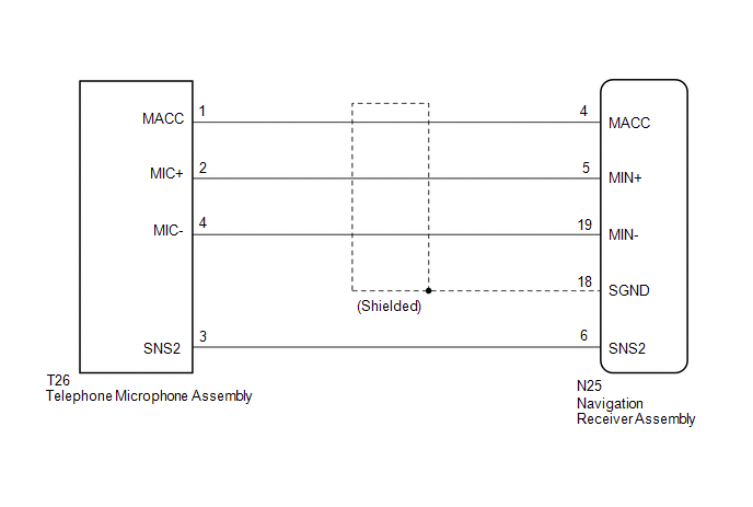
The navigation receiver assembly and telephone microphone assembly are connected to each other using the microphone connection detection signal lines.
Using this circuit, the navigation receiver assembly sends power to the telephone microphone assembly and the telephone microphone assembly sends microphone signals to the navigation receiver assembly.
WIRING DIAGRAM
PROCEDURE
|
1. |
CHECK MICROPHONE |
|
(a) Enter the "Microphone Check" screen. Refer to Check Microphone in
Operation Check (See page |
|
.gif) ).
)..png)
(b) When a voice is input into the microphone, check that the microphone input level meter changes according to the input voice.
OK:
Check result is normal.
| OK | .gif) |
PROCEED TO NEXT SUSPECTED AREA SHOWN IN PROBLEM SYMPTOMS TABLE |
|
.gif)
|
2. |
CHECK HARNESS AND CONNECTOR (NAVIGATION RECEIVER ASSEMBLY - TELEPHONE MICROPHONE ASSEMBLY) |
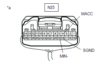
(a) Disconnect the N25 navigation receiver assembly connector.
(b) Disconnect the T26 telephone microphone assembly connector.
(c) Measure the resistance according to the value(s) in the table below.
Standard Resistance:
|
Tester Connection |
Condition |
Specified Condition |
|---|---|---|
|
N25-4 (MACC) - T26-1 (MACC) |
Always |
Below 1 Ω |
|
N25-5 (MIN+) - T26-2 (MIC+) |
Always |
Below 1 Ω |
|
N25-19 (MIN-) - T26-4 (MIC-) |
Always |
Below 1 Ω |
|
N25-6 (SNS2) - T26-3 (SNS2) |
Always |
Below 1 Ω |
|
N25-4 (MACC) - Body ground |
Always |
10 kΩ or higher |
|
N25-5 (MIN+) - Body ground |
Always |
10 kΩ or higher |
|
N25-19 (MIN-) - Body ground |
Always |
10 kΩ or higher |
|
N25-18 (SGND) - Body ground |
Always |
10 kΩ or higher |
|
N25-6 (SNS2) - Body ground |
Always |
10 kΩ or higher |
(d) Reconnect the navigation receiver assembly connector.
(e) Reconnect the telephone microphone assembly connector.
| NG | |
REPAIR OR REPLACE HARNESS OR CONNECTOR |
|
|
3. |
INSPECT NAVIGATION RECEIVER ASSEMBLY |
|
(a) Measure the voltage according to the value(s) in the table below. Standard Voltage:
|
|
(b) Measure the resistance according to the value(s) in the table below.
Standard Resistance:
|
Tester Connection |
Condition |
Specified Condition |
|---|---|---|
|
N25-19 (MIN-) - Body ground |
Always |
Below 1 Ω |
|
N25-18 (SGND) - Body ground |
Always |
Below 1 Ω |
| NG | |
REPLACE NAVIGATION RECEIVER ASSEMBLY |
|
|
4. |
INSPECT TELEPHONE MICROPHONE ASSEMBLY |
|
(a) Remove the telephone microphone assembly (See page
|
|
.png)
(b) Measure the resistance according to the value(s) in the table below.
Standard Resistance:
|
Tester Connection |
Condition |
Specified Condition |
|---|---|---|
|
3 (SNS2) - 4 (MIC-) |
Always |
Below 1 Ω |
(c) Install the telephone microphone assembly.
| NG | |
REPLACE TELEPHONE MICROPHONE ASSEMBLY |
|
|
5. |
INSPECT TELEPHONE MICROPHONE ASSEMBLY |
|
(a) Turn the ignition switch to ACC. |
|
.png)
(b) Connect an oscilloscope to terminals 2 (MIC+) and 4 (MIC-) of the telephone microphone assembly connector.
(c) Check the waveform of the telephone microphone assembly using the oscilloscope.
Result|
Result |
Proceed to |
|---|---|
|
A waveform synchronized with the voice input to the telephone microphone assembly is output |
A |
|
A waveform synchronized with the voice input to the telephone microphone assembly is not output |
B |
| A | |
PROCEED TO NEXT SUSPECTED AREA SHOWN IN PROBLEM SYMPTOMS TABLE |
| B | |
REPLACE TELEPHONE MICROPHONE ASSEMBLY |
 Vehicle Speed Signal Circuit between Stereo Component Amplifier and Combination
Meter
Vehicle Speed Signal Circuit between Stereo Component Amplifier and Combination
Meter
DESCRIPTION
The stereo component amplifier assembly receives a vehicle speed signal from
the combination meter assembly to control the ASL function.
HINT:
A voltage of 12 V or 5 V is outp ...
 Radio Receiver Power Source Circuit
DESCRIPTION
This is the power source circuit to operate the navigation receiver assembly.
WIRING DIAGRAM
CAUTION / NOTICE / HINT
NOTICE:
Inspect the fuses for circuits related to this s ...
Other materials:
How To Proceed With Troubleshooting
CAUTION / NOTICE / HINT
HINT:
The ECM of this system is connected to the CAN communication system.
Therefore, before starting troubleshooting, make sure to check that there
is no trouble in the CAN and multiplex communication system.
*: Use the Techstream.
PROCEDURE
...
Satellite Radio Broadcast cannot be Received
CAUTION / NOTICE / HINT
NOTICE:
Some satellite radio broadcasts require payment. A contract must be
made between a satellite radio company and the user. If the contract expires,
it will not be possible to listen to the broadcast.
After replacing the stereo component tuner assem ...
Precaution
PRECAUTION
1. IGNITION SWITCH EXPRESSIONS
(a) The type of ignition switch used on this model differs according to the specifications
of the vehicle. The expressions listed in the table below are used in this section.
Expression
Ignition Switch (Position)
Engine ...
