Toyota Tacoma (2015-2018) Service Manual: Installation
INSTALLATION
CAUTION / NOTICE / HINT
CAUTION:
Some of these service operations affect the SRS airbag system. Read the precautionary notices concerning the SRS airbag system before servicing.
Click here .gif)
PROCEDURE
1. INSTALL FRONT SEAT INNER BELT ASSEMBLY
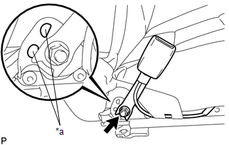
(a) for Driver Side:
(1) Install the front seat belt anchor plate.
|
(2) Install the front seat inner belt assembly with the nut. Text in Illustration
Torque: 42 N·m {428 kgf·cm, 31 ft·lbf} NOTICE: Do not allow the anchor part of the front seat inner belt assembly to overlap the protruding part of the front seat with adjuster frame. |
|
(3) Check that the front seat inner belt rotates smoothly.
(4) Connect the seat position sensor connector.
(5) Engage the 3 clamps.
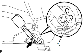
(b) for Front Passenger Side:
(1) Install the front seat belt anchor plate.
|
(2) Install the front seat inner belt assembly with the nut. Text in Illustration
Torque: 42 N·m {428 kgf·cm, 31 ft·lbf} NOTICE: Do not allow the anchor part of the front seat inner belt assembly to overlap the protruding part of the front seat with adjuster frame. |
|
(3) Check that the front seat inner belt rotates smoothly.
(4) Engage the 2 clamps.
(5) Connect the connector.
2. INSTALL FRONT SEAT ASSEMBLY
(a) for Driver Side:
Click here
(b) for Front Passenger Side:
Click here
3. INSTALL SEAT TRACK COVER
(a) for Driver Side:
Click here
(b) for Front Passenger Side:
Click here
4. CONNECT CABLE TO NEGATIVE BATTERY TERMINAL
Torque:
5.4 N·m {55 kgf·cm, 48 in·lbf}
NOTICE:
When disconnecting the cable, some systems need to be initialized after the cable is reconnected.
Click here
5. INSPECT SRS WARNING LIGHT
Click here
 Removal
REMOVAL
CAUTION / NOTICE / HINT
CAUTION:
Some of these service operations affect the SRS airbag system. Read the precautionary
notices concerning the SRS airbag system before servicing.
Click he ...

Other materials:
Problem Symptoms Table
PROBLEM SYMPTOMS TABLE
HINT:
Use the table below to help determine the cause of problem symptoms.
If multiple suspected areas are listed, the potential causes of the symptoms
are listed in order of probability in the "Suspected Area" column of the
table. Check each sy ...
Fail-safe Chart
FAIL-SAFE CHART
If any of the following DTCs are stored, the ECM enters fail-safe mode to allow
the vehicle to be driven temporarily.
DTC
Fail-safe Operation
Fail-safe Deactivation Condition
P161A87
Generator command is maintained
...
Touch Panel Switch does not Function
PROCEDURE
1.
CHECK MULTI-DISPLAY
(a) Check if there is any foreign matter caught between the display and exterior
frame of the multi-display.
OK:
No foreign matter is caught between the display and exterior frame of the multi-display.
HINT:
If there is foreig ...
