Toyota Tacoma (2015-2018) Service Manual: Distance Control Switch Circuit
DESCRIPTION
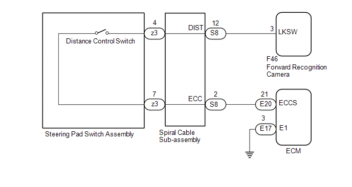
The distance control switch is used to set the distance for vehicle-to-vehicle distance control mode. The distance control switch is installed in the steering pad switch assembly. The vehicle-to-vehicle distance set value can be changed by operating the steering pad switch assembly (distance control switch) while the dynamic radar cruise control system is controlling vehicle speed in vehicle-to-vehicle distance control mode.
WIRING DIAGRAM
CAUTION / NOTICE / HINT
NOTICE:
- Before replacing the ECM, refer to Registration.
w/o Smart Key System: Click here
.gif)
w/ Smart Key System: Click here
- The vehicle is equipped with a Supplemental Restraint System (SRS) which
includes components such as airbags. Before servicing (including removal
or installation of parts), be sure to read the precaution for Supplemental
Restraint System.
Click here
- When replacing the forward recognition camera, always replace it with a new one. If a forward recognition camera which was installed to another vehicle is used, the information stored in the forward recognition camera will not match the information from the vehicle. As a result, a DTC may be stored.
- If the forward recognition camera has been replaced with a new one,
be sure to perform Forward Recognition Camera Learning.
Click here
PROCEDURE
|
1. |
READ VALUE ON TECHSTREAM (DISTANCE CONTROL SWITCH) |
(a) Connect the Techstream to the DLC3.
(b) Turn the ignition switch to ON.
(c) Turn the Techstream on.
(d) Enter the following menus: Powertrain / Radar Cruise 2 / Data List.
(e) Read the Data List according to the display on the Techstream.
Powertrain > Radar Cruise2 > Data List
|
Tester Display |
Measurement Item |
Range |
Normal Condition |
Diagnostic Note |
|---|---|---|---|---|
|
Distance Control Switch |
Distance control switch signal |
ON or OFF |
ON: Distance control switch on OFF: Distance control switch off |
- |
OK:
The Data List item shown in the table changes according to the operation of the steering pad switch assembly (distance control switch).
| OK | .gif) |
PROCEED TO NEXT SUSPECTED AREA SHOWN IN PROBLEM SYMPTOMS TABLE |
|
.gif)
|
2. |
INSPECT STEERING PAD SWITCH ASSEMBLY |
(a) Remove the steering pad switch assembly.
Click here
(b) Inspect the steering pad switch assembly.
Click here
| NG | |
REPLACE STEERING PAD SWITCH ASSEMBLY |
|
|
3. |
INSPECT SPIRAL CABLE WITH SENSOR SUB-ASSEMBLY |
(a) Remove the spiral cable with sensor sub-assembly.
Click here
(b) Inspect the spiral cable with sensor sub-assembly.
Click here
| NG | |
REPLACE SPIRAL CABLE WITH SENSOR SUB-ASSEMBLY |
|
|
4. |
CHECK HARNESS AND CONNECTOR (SPIRAL CABLE WITH SENSOR SUB-ASSEMBLY - FORWARD RECOGNITION CAMERA, ECM AND BODY GROUND) |
(a) Disconnect the S8 spiral cable with sensor sub-assembly connector.
(b) Disconnect the F46 forward recognition camera connector.
(c) Disconnect the E20 ECM connector.
(d) Measure the resistance according to the value(s) in the table below.
Standard Resistance:
|
Tester Connection |
Condition |
Specified Condition |
|---|---|---|
|
S8-12 (DIST) - F46-3 (LKSW) |
Always |
Below 1 Ω |
|
S8-2 (ECC) - E20-21 (ECCS) |
Always |
Below 1 Ω |
|
S8-12 (DIST) or F46-3 (LKSW) - Body ground |
Always |
10 kΩ or higher |
|
S8-2 (ECC) or E20-21 (ECCS) - Body ground |
Always |
10 kΩ or higher |
| NG | |
REPAIR OR REPLACE HARNESS OR CONNECTOR |
|
|
5. |
CHECK HARNESS AND CONNECTOR (ECM - BODY GROUND) |
(a) Disconnect the E20 ECM connector.
(b) Measure the resistance according to the value(s) in the table below.
Standard Resistance:
|
Tester Connection |
Condition |
Specified Condition |
|---|---|---|
|
S8-2 (ECC) or E20-21 (E1) -Body ground |
Always |
Below 1 Ω |
| NG | |
REPAIR OR REPLACE HARNESS OR CONNECTOR |
|
|
6. |
CHECK ECM (ECM TERMINALS) |
(a) Disconnect the E20 and E17 ECM connectors.
(b) Measure the resistance according to the value(s) in the table below.
Standard Resistance:
|
Tester Connection |
Condition |
Specified Condition |
|---|---|---|
|
E20-21 (ECCS) - E17-3 (E1) |
Always |
Below 1 Ω |
| OK | |
REPLACE FORWARD RECOGNITION CAMERA |
| NG | |
REPLACE ECM |
 Cruise Control Switch Circuit
DESCRIPTION
The cruise control main switch is used to turn the dynamic radar cruise control
system on and off, as well as operate 7 functions: SET, - (COAST), TAP-DOWN, RES
(RESUME), + (ACCEL), T ...
 Cruise Main Indicator Light Circuit
DESCRIPTION
When the dynamic radar cruise control system is turned on using the cruise control
main switch (ON-OFF button), the cruise control indicator (vehicle-to-vehicle distance
control mode) ...
Other materials:
Portable Player cannot be Registered
CAUTION / NOTICE / HINT
HINT:
Some versions of "Bluetooth" compatible audio players may not function, or the
function may be limited using the radio and display receiver assembly, even if the
portable audio player itself can play files (See page
).
PROCEDURE
1.
...
Inspection
INSPECTION
PROCEDURE
1. INSPECT RADIATOR CORE SUB-ASSEMBLY
Check the core plate for damage.
Text in Illustration
*1
Core Plate
*2
Radiator Core
If the sides of the core plate groove are deformed, it is impossible
to reassem ...
System Description
SYSTEM DESCRIPTION
1. LIN COMMUNICATION SYSTEM DESCRIPTION
The LIN communication system is used for communication between the components
in the tables below. If communication cannot be performed through LIN communication
because of an open in the communication lines or other reasons, the maste ...
