
Toyota Tacoma (2015-2018) Service Manual: Removal
REMOVAL
PROCEDURE
1. REMOVE FUEL TANK ASSEMBLY
Click here .gif)
2. DISCONNECT FUEL TANK MAIN TUBE SUB-ASSEMBLY
Click here
3. REMOVE FUEL PUMP GAUGE RETAINER
NOTICE:
Before performing these procedures, first cover the connectors and tube joints of the fuel suction tube with pump and gauge assembly with vinyl tape and then clean away any mud or other substances that may be adhering in order to prevent foreign matter from contaminating the fuel system.
(a) Place paint marks on the fuel suction tube with pump and gauge assembly and fuel tank assembly as shown in the illustration.
NOTICE:
- The fuel suction tube with pump and gauge assembly has 2 protrusions that engage with 2 notches on the fuel tank assembly to ensure correct alignment and to prevent the fuel suction tube with pump and gauge assembly from turning during installation and removal of the fuel pump gauge retainer.
- If the fuel pump gauge retainer is turned with the fuel suction tube with pump and gauge assembly misaligned, the fuel suction tube with pump and gauge assembly will turn with the fuel pump gauge retainer and may be damaged.
- The paint marks are used to ensure that the fuel suction tube with pump and gauge assembly does not turn with the fuel pump gauge retainer.
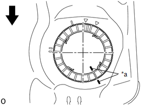
|
*a |
Paint Mark |
.png) |
Front Side of Vehicle |
(b) Install SST to the fuel pump gauge retainer.
|
(1) Set 4 SST (claw set) to the fuel pump gauge retainer. SST: 09808-14031 09808-01080 09808-01090 09808-01100 NOTICE:
|
|
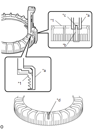
(2) Push SST (claw set) against the fuel pump gauge retainer and tighten SST (bolt).
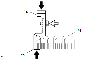
|
*1 |
Fuel Pump Gauge Retainer |
|
*a |
SST (Claw Set) |
|
*b |
Hook |
|
|
Push |
.png) |
SST (Bolt) |
(3) Temporarily install SST (plate) to SST (claw set) with 4 SST (bolt).
SST: 09808-14031
09808-01030
09808-01090
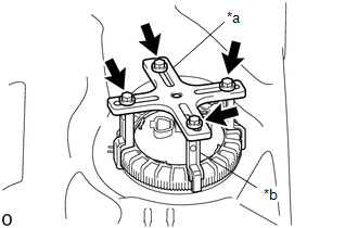
|
*a |
SST (Plate) |
|
*b |
SST (Claw Set) |
|
|
SST (Bolt) |
(4) Adjust the position of SST (claw set) so that the hole in SST (plate) for installing SST (handle) is in the center of the fuel pump gauge retainer.
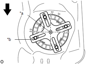
|
*a |
Center Point of Fuel Pump Gauge Retainer |
|
*b |
SST (Plate) |
|
|
Front Side of Vehicle |
(5) Press SST (claw set) against the rib of the fuel pump gauge retainer and tighten SST (bolt).
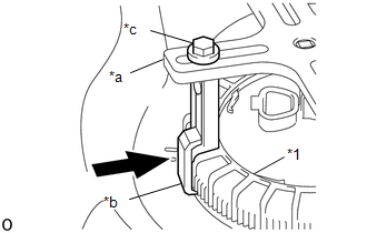
|
*1 |
Fuel Pump Gauge Retainer |
|
*a |
SST (Plate) |
|
*b |
SST (Claw Set) |
|
*c |
SST (Bolt) |
|
|
Press |
(6) Install SST (handle) to SST (plate).
SST: 09808-14031
09808-01010
09808-01020
(c) Slowly loosen the fuel pump gauge retainer by approximately 90°.
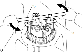
|
*a |
SST (Plate) |
|
*b |
SST (Handle) |
|
|
Loosen |
NOTICE:
Do not spin SST too fast or use an impact wrench as this may result in damage to components.
(d) While one person loosens the fuel pump gauge retainer, have another person press down the rising fuel suction tube with pump and gauge assembly, securely insert the protrusion of the fuel suction tube with pump and gauge assembly into the groove of the fuel tank assembly, and then remove the fuel pump gauge retainer while making sure that the fuel suction tube with pump and gauge assembly is properly aligned.
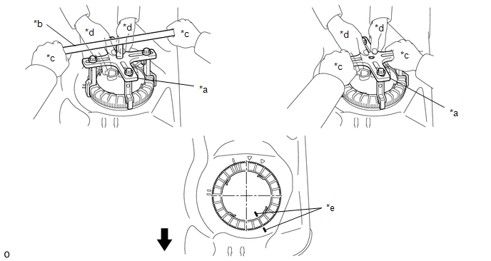
|
*a |
SST (Plate) |
*b |
SST (Handle) |
|
*c |
One Person in Charge of Loosening |
*d |
One Person in Charge of Pressing Down |
|
*e |
Paint Mark |
- |
- |
|
|
Front Side of Vehicle |
- |
- |
NOTICE:
- The fuel suction tube with pump and gauge assembly is pressed against the underside of the fuel tank assembly by a spring, and the constant upward pressure applied by this spring causes the fuel suction tube with pump and gauge assembly to rise up.
- If the fuel pump gauge retainer is turned while the fuel suction tube with pump and gauge assembly and fuel tank assembly are not correctly aligned, the fuel suction tube with pump and gauge assembly will move with the fuel pump gauge retainer, and the fuel suction tube with pump and gauge assembly and fuel tank assembly may both be damaged.
- Do not turn the fuel pump gauge retainer if the paint marks become misaligned.
4. REMOVE FUEL SUCTION TUBE WITH PUMP AND GAUGE ASSEMBLY
(a) Remove the fuel suction tube with pump and gauge assembly from the fuel tank assembly.
NOTICE:
Be careful not to bend the arm of the fuel sender gauge assembly.
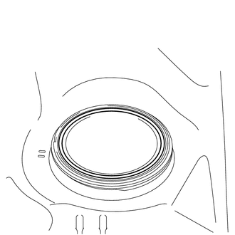
5. REMOVE FUEL SUCTION TUBE SET GASKET
|
(a) Remove the fuel suction tube set gasket from the fuel tank assembly. |
|
 Disassembly
DISASSEMBLY
CAUTION / NOTICE / HINT
NOTICE:
Do not try to remove the black nylon tube as it is welded to the fuel suction
tube assembly (See page
).
PROCEDURE
1. REMOVE FUEL SENDER GAUGE ASS ...
 Inspection
INSPECTION
PROCEDURE
1. INSPECT FUEL PUMP
(a) Inspect the resistance of the fuel pump.
(1) Measure the resistance according to the value(s) in the table below.
Text in Illustration ...
Other materials:
Black Screen
PROCEDURE
1.
CHECK DISPLAY SETTING
(a) Check that the display is not in "Screen Off" mode.
OK:
The display setting is not in "Screen Off" mode.
NG
CHANGE SCREEN TO SCREEN ON MODE
OK
...
Terminals Of Ecm
TERMINALS OF ECM
1. ECM
HINT:
The standard voltage between each pair of ECM terminals is shown in the table
below. In the table, first follow the information under "Condition". Look under
"Terminal No. (Symbol)" for the terminals to be inspected. The standard voltage
b ...
Problem Symptoms Table
PROBLEM SYMPTOMS TABLE
Use the table below to help determine the cause of problem symptoms. If multiple
suspected areas are listed, the potential causes of the symptoms are listed in order
of probability in the "Suspected Area" column of the table. Check each symptom by
checking the ...
