Toyota Tacoma (2015-2018) Service Manual: Disassembly
DISASSEMBLY
CAUTION / NOTICE / HINT
NOTICE:
Do not try to remove the black nylon tube as it is welded to the fuel suction
tube assembly (See page .gif) ).
).
PROCEDURE
1. REMOVE FUEL SENDER GAUGE ASSEMBLY
2. REMOVE NO. 1 FUEL SUB-TANK
|
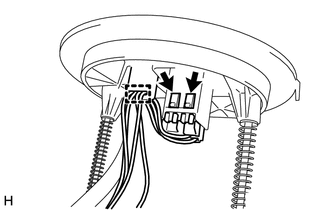
(a) Disconnect the 2 fuel pump connectors. |
|
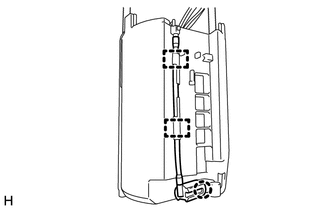
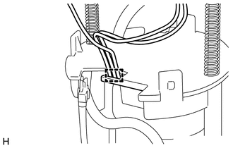
(b) Disengage the clamp and disconnect the wire harness.
|
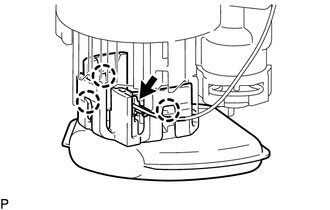
(c) Disengage the claw and 2 clamps and disconnect the jet pump nozzle. |
|
|
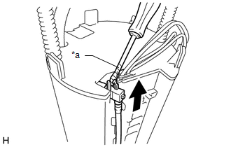
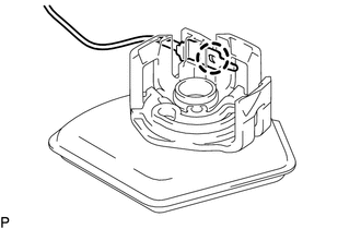
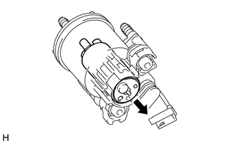
(d) Using a screwdriver with its tip wrapped with protective tape, disconnect the jet pump from the No. 1 fuel sub-tank. Text in Illustration
NOTICE: The O-ring is installed firmly between the jet pump and No. 1 fuel sub-tank. Therefore, the jet pump and No. 1 fuel sub-tank should be separated carefully using a screwdriver. |
|
|
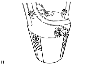
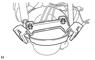
(e) Disengage the 5 claws and remove the No. 1 fuel sub-tank. NOTICE: Do not damage the No. 1 fuel sub-tank. |
|
3. REMOVE FUEL PUMP FILTER
|
(a) Disengage the 3 claws and disconnect the fuel pump filter from the fuel filter case. |
|
|
(b) Disengage the claw and disconnect the fuel pump harness from the fuel pump filter. |
|
4. REMOVE FUEL PUMP
|
(a) Disengage the clamp and disconnect the wire harness. |
|
|
(b) Disengage the 2 claws and remove the No. 1 fuel suction support from the fuel filter case. |
|
|
(c) Remove the fuel pump from the fuel filter case. |
|
|
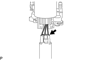
(d) Disconnect the fuel pump harness connector and remove the fuel pump harness from the fuel pump. |
|
|
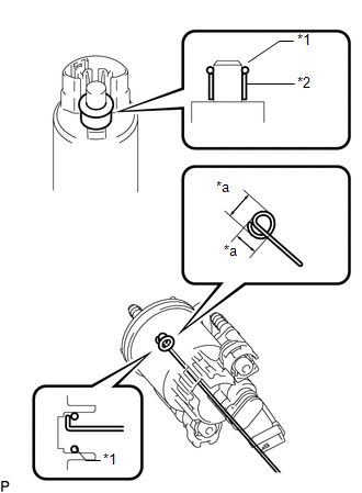
(e) Remove the O-ring and fuel pump spacer from the fuel pump. Text in Illustration
NOTICE: Be careful not to damage the sealing surface. HINT: If the O-ring still remains in the fuel filter, remove it using a wire tip (1 mm diameter) that is formed as shown in the illustration. |
|
 Components
COMPONENTS
ILLUSTRATION
ILLUSTRATION
...
 Removal
REMOVAL
PROCEDURE
1. REMOVE FUEL TANK ASSEMBLY
Click here
2. DISCONNECT FUEL TANK MAIN TUBE SUB-ASSEMBLY
Click here
3. REMOVE FUEL PUMP GAUGE RETAINER
NOTICE:
Before performing these proce ...
Other materials:
Installation
INSTALLATION
PROCEDURE
1. INSTALL POWER STEERING LINK
(a) Insert the power steering link into the vehicle in the order shown in the
illustration.
Install in this Direction (1)
Install in this Direction (2)
(b) Temporarily install the po ...
Vehicle Speed Signal Circuit between Stereo Component Amplifier and Combination
Meter
DESCRIPTION
The stereo component amplifier assembly receives a vehicle speed signal from
the combination meter assembly to control the ASL function.
HINT:
A voltage of 12 V or 5 V is output from each ECU and then input to the
combination meter assembly. The signal is changed to a pu ...
Cleaning and protecting the vehicle interior
The following procedures will help protect your vehicle’s interior and keep
it in top condition:
■ Protecting the vehicle interior
Remove dirt and dust using a vacuum cleaner. Wipe dirty surfaces with a cloth
dampened with lukewarm water.
■ Cleaning the leather areas
● Re ...
