Toyota Tacoma (2015-2018) Service Manual: Components
COMPONENTS
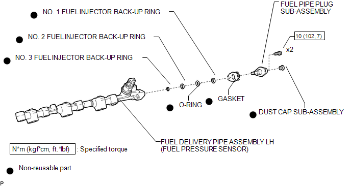
ILLUSTRATION

 Removal
REMOVAL
PROCEDURE
1. REMOVE FUEL DELIVERY PIPE ASSEMBLY LH (FUEL PRESSURE SENSOR)
(See page )
NOTICE:
Do not remove the fuel pressure sensor from the fuel delivery pipe sub-assembly
...
Other materials:
Open in Occupant Classification ECU Battery Positive Line (B1794)
DESCRIPTION
DTC B1794 is set when a malfunction is detected in the occupant detection ECU.
DTC No.
DTC Detections Conditions
Trouble Areas
B1794
Occupant detection ECU circuit malfunction
Occupant detection ECU malfuncti ...
Open in ABS Solenoid Relay Circuit (C146E,C146F)
DESCRIPTION
The ABS solenoid relay is built into the master cylinder solenoid.
This relay supplies power to each ABS solenoid. After the ignition switch is
turned ON, if the initial check is OK, the relay turns on.
DTC No.
DTC Detecting Conditions
Trouble Areas
...
Installation
INSTALLATION
PROCEDURE
1. INSTALL ENGINE COOLANT TEMPERATURE SENSOR
2. INSTALL ENGINE OIL PRESSURE SWITCH ASSEMBLY
3. INSTALL IGNITION COIL ASSEMBLY
4. INSTALL FUEL INJECTOR SEAL
5. INSTALL FUEL INJECTOR ASSEMBLY
6. INSTALL FUEL DELIVERY PIPE RH
7. INSTALL FUEL DELIVERY PIP ...
