Toyota Tacoma (2015-2018) Service Manual: Room Light Assembly
Components
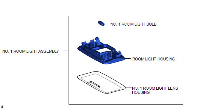
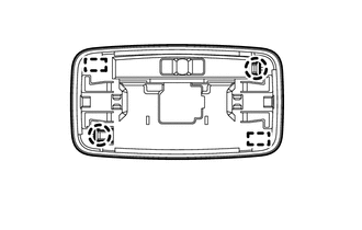
COMPONENTS
ILLUSTRATION
Removal
REMOVAL
PROCEDURE
1. REMOVE NO. 1 ROOM LIGHT ASSEMBLY
|
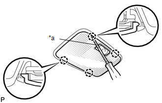
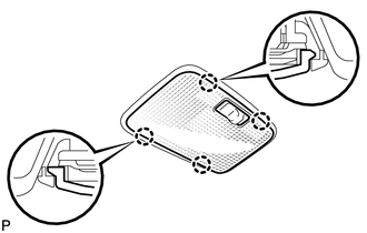
(a) Using a screwdriver with its tip wrapped in protective tape, disengage the 4 claws to remove the No. 1 room light lens. Text in Illustration
|
|
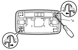
(b) Using a screwdriver with its tip wrapped in protective tape, disengage the 2 claws and 2 guides to separate the No. 1 room light housing as shown in the illustration.
 Text in Illustration
|
*a |
Protective Tape |
.png) |
Push |
(c) Disengage the guide to separate the wire harness.
|
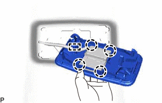
(d) Disengage the 4 claws to separate the No. 1 room light housing from the room light switch base. |
|
2. REMOVE NO. 1 ROOM LIGHT BULB
(a) Remove the No. 1 room light bulb.
Installation
INSTALLATION
PROCEDURE
1. INSTALL NO. 1 ROOM LIGHT BULB
(a) Install the No. 1 room light bulb.
2. INSTALL NO. 1 ROOM LIGHT ASSEMBLY
(a) Engage the 4 claws to install the No. 1 room light housing to the room light switch base.
(b) Engage the guide to install the wire harness.
|
(c) Engage the 2 guides and 2 claws to install the No. 1 room light housing. |
|
|
(d) Engage the 4 claws to install the No. 1 room light lens. |
|
 Rear Door Courtesy Switch
Inspection
INSPECTION
PROCEDURE
1. INSPECT REAR DOOR COURTESY SWITCH
(a) Check the resistance.
(1) Measure the resistance using an ohmmeter, and check the results in accordance
with the value ...
 Side Turn Signal Light Assembly
Components
COMPONENTS
ILLUSTRATION
Removal
REMOVAL
CAUTION / NOTICE / HINT
HINT:
Use the same procedure for both the RH and LH sides.
The procedure described below is for the ...
Other materials:
Disposal
DISPOSAL
CAUTION / NOTICE / HINT
CAUTION:
Before performing pre-disposal deployment of any SRS part, review and closely
follow all applicable environmental and hazardous material regulations. Pre-disposal
deployment may be considered hazardous material treatment.
PROCEDURE
1. PRECAUTION
...
Installation
INSTALLATION
PROCEDURE
1. INSTALL OCCUPANT DETECTION ECU
(a) Check that the ignition switch is OFF.
(b) Check that the cable is disconnected from the battery negative (-) terminal
is disconnected.
CAUTION:
After removing the cable from the terminal, wait for at least 90 seconds before
star ...
Glass Position Initialization Incomplete (B2313)
DESCRIPTION
The power window regulator motor assembly is operated by the power window regulator
master switch assembly or power window regulator switch assembly. The power window
regulator motor assembly has motor, regulator and ECU functions.
When the ECU determines that the power window regu ...
