Toyota Tacoma (2015-2018) Service Manual: Removal
REMOVAL
PROCEDURE
1. REMOVE INTAKE AIR SURGE TANK ASSEMBLY
(See page .gif) )
)
2. DISCONNECT NO. 2 FUEL TUBE SUB-ASSEMBLY
|
(a) Disengage the 2 clamps. |
|
(b) Disconnect the No. 2 fuel tube sub-assembly from the fuel tube sub-assembly
(See page ).
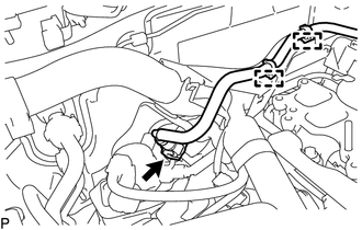
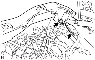
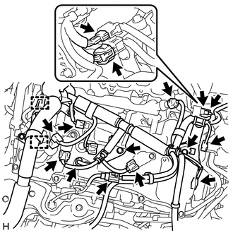
3. DISCONNECT ENGINE WIRE
|
(a) for LH Side: (1) Remove the nut and disconnect the engine wire from the cylinder head cover sub-assembly LH. (2) Disconnect the connector. |
|
|
(b) for RH Side: (1) Disengage the 2 clamps. (2) Disconnect the 13 connectors. (3) Remove the 2 bolts and disconnect the engine wire. |
|
4. REMOVE FUEL DELIVERY PIPE SUB-ASSEMBLY
NOTICE:
- Do not remove the fuel pressure sensor from the fuel delivery pipe sub-assembly.
- If a fuel pressure sensor is removed, replace the fuel delivery pipe sub-assembly (fuel pressure sensor) with a new one.
|
(a) Disconnect the connector. |
|
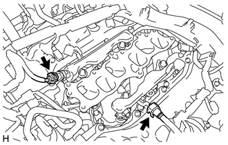
(b) Disconnect the No. 1 fuel tube sub-assembly from the fuel delivery pipe sub-assembly
(See page ).
|
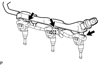
(c) Remove the 4 bolts and fuel delivery pipe sub-assembly. NOTICE: When removing the fuel delivery pipe sub-assembly, hold the pipe by both ends and pull it straight upward. |
|
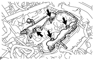
(d) Remove the 4 No. 1 delivery pipe spacers from the intake manifold.
(e) Remove the 6 injector vibration insulators from the intake manifold.
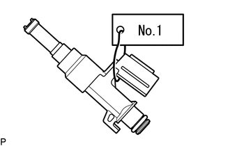
5. REMOVE FUEL INJECTOR ASSEMBLY
NOTICE:
For reinstallation, attach a tag or label to the injector shaft.
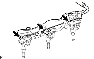
(a) for LH Side:
(1) Disengage the clamp.
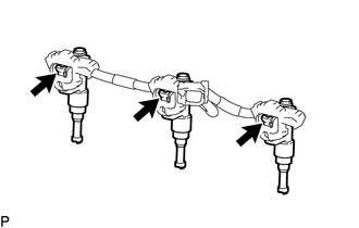
(2) Remove the 3 fuel injector assemblies with No. 5 engine wire from the fuel delivery pipe sub-assembly.
|
(3) Disconnect the 3 connectors and remove the 3 fuel injector assemblies. |
|
|
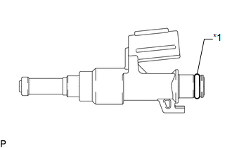
(4) Remove the O-ring from the fuel injector assembly. Text in Illustration
|
|
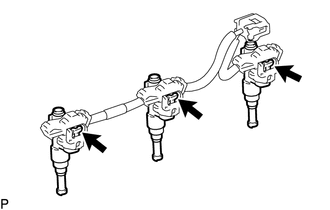
(b) for RH Side:
(1) Disengage the clamp.
(2) Remove the 3 fuel injector assemblies with No. 5 engine wire from the fuel delivery pipe sub-assembly.
|
(3) Disconnect the 3 connectors and remove the 3 fuel injector assemblies. |
|
|
(4) Remove the O-ring from the fuel injector assembly. Text in Illustration
|
|
 Inspection
INSPECTION
PROCEDURE
1. INSPECT FUEL INJECTOR ASSEMBLY
(a) Measure the resistance according to the value(s) in the table below.
Standard Resistance:
Tester Connection
Condi ...
 Installation
INSTALLATION
CAUTION / NOTICE / HINT
HINT:
Perform "Inspection After Repairs" after replacing the fuel injector assembly
(See page ).
PROCEDURE
1. INSTALL FUEL INJECTOR ASSEMBLY
HIN ...
Other materials:
Data List / Active Test
DATA LIST / ACTIVE TEST
NOTICE:
In the table below, the values listed under "Normal Condition" are reference
values. Do not depend solely on these reference values when deciding whether a part
is faulty or not.
HINT:
Using the Techstream to read the Data List allows the values or s ...
Communication Error from VSC to ECM (P1630)
DESCRIPTION
The skid control ECU (brake actuator assembly) sends signals such as cruise control
cancel signals and brake demand response signals to the ECM when the dynamic radar
cruise control system is operating.
DTC No.
Detection Item
DTC Detection Condition ...
Microphone Circuit between Microphone and Radio Receiver
DESCRIPTION
The navigation receiver assembly and telephone microphone assembly are connected
to each other using the microphone connection detection signal lines.
Using this circuit, the navigation receiver assembly sends power to the telephone
microphone assembly and the telephone microphone ...
