Toyota Tacoma (2015-2018) Service Manual: Installation
INSTALLATION
CAUTION / NOTICE / HINT
HINT:
Perform "Inspection After Repairs" after replacing the fuel injector assembly
(See page .gif) ).
).
PROCEDURE
1. INSTALL FUEL INJECTOR ASSEMBLY
HINT:
Perform "Inspection After Repairs" after replacing the fuel injector assembly
(See page ).
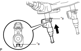
(a) Apply gasoline to new O-rings and install them to each injector.
NOTICE:
Check that there is no damage or foreign material in the groove of the injector when installing the O-rings.
|
(b) Install the fuel injector assemblies to the fuel delivery pipe sub-assembly. Text in Illustration
NOTICE:
|
|
2. INSTALL FUEL DELIVERY PIPE SUB-ASSEMBLY
NOTICE:
- Do not remove the fuel pressure sensor from the fuel delivery pipe sub-assembly.
- If a fuel pressure sensor is removed, replace the fuel delivery pipe sub-assembly (fuel pressure sensor) with a new one.
(a) Install 6 new injection vibration insulators to the intake manifold.
(b) Install the 4 No. 1 delivery pipe spacers to the intake manifold.
(c) Install the fuel delivery pipe sub-assembly (with fuel injector assembly) to the intake manifold.
NOTICE:
Be careful not to twist the O-ring.
|
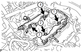
(d) Install the fuel injector assemblies to the fuel delivery pipe sub-assemblies with the 4 bolts in the order shown in the illustration. Torque: 17 N·m {173 kgf·cm, 13 ft·lbf} |
|
(e) Connect the No. 1 fuel tube sub-assembly to the fuel delivery pipe sub-assembly
(See page ).
(f) Connect the connector.
3. CONNECT ENGINE WIRE
(a) for RH Side:
(1) Connect the engine wire with the 2 bolts.
Torque:
8.0 N·m {82 kgf·cm, 71 in·lbf}
(2) Connect the 13 connectors.
(3) Engage the 2 clamps.
(b) for LH Side:
(1) Connect the connector.
(2) Connect the engine wire to the cylinder head cover sub-assembly LH with the nut.
Torque:
8.0 N·m {82 kgf·cm, 71 in·lbf}
4. CONNECT NO. 2 FUEL TUBE SUB-ASSEMBLY
(a) Connect the No. 2 fuel tube sub-assembly to the fuel tube sub-assembly (See
page ).
(b) Engage the 2 clamps.
5. INSTALL INTAKE AIR SURGE TANK ASSEMBLY
(See page )
 Removal
REMOVAL
PROCEDURE
1. REMOVE INTAKE AIR SURGE TANK ASSEMBLY
(See page )
2. DISCONNECT NO. 2 FUEL TUBE SUB-ASSEMBLY
(a) Disengage the 2 clamps.
...
 Fuel Main Valve
Components
COMPONENTS
ILLUSTRATION
Removal
REMOVAL
PROCEDURE
1. REMOVE FUEL SUCTION TUBE WITH PUMP AND GAUGE ASSEMBLY
(See page )
2. REMOVE FUEL SENDER GAUGE ASSEMBLY
3. REMOVE NO. ...
Other materials:
Installation
INSTALLATION
PROCEDURE
1. REMOVE MONOLITHIC CONVERTER PROTECTOR
(a) Install the upper monolithic converter protector and lower monolithic converter
protector with the 2 bolts and 2 nuts.
Torque:
11 N·m {107 kgf·cm, 8 ft·lbf}
(b) Install the clamp with the bolt as shown in the ...
Removal
REMOVAL
CAUTION / NOTICE / HINT
HINT:
Use the same procedure for the RH side and LH side.
The following procedure is for the LH side.
PROCEDURE
1. PRECAUTION
NOTICE:
After turning the ignition switch off, waiting time may be required before disconnecting
the cable from the ...
Transfer L4 Position Switch Circuit (C1268)
DESCRIPTION
A-TRAC is activated if wheel skid is detected while the transfer is in the L4
position.
DTC Code
DTC Detecting Condition
Trouble Areas
C1268
L4 detection switch signal input to skid control ECU (master cylinder
solenoid ...
