Toyota Tacoma (2015-2018) Service Manual: Removal
REMOVAL
PROCEDURE
1. REMOVE FUEL TANK ASSEMBLY
Click here .gif)
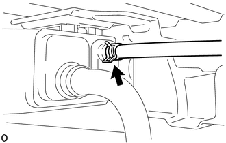
2. DISCONNECT CHARCOAL CANISTER FUEL HOSE
|
(a) Loosen the hose clip and disconnect the charcoal canister fuel hose. |
|
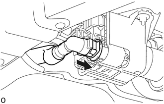
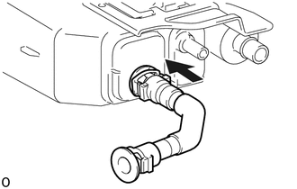
3. DISCONNECT FUEL TANK VENT HOSE
(a) Push the fuel tank vent hose deep inside.
.png) |
Push |
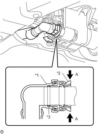
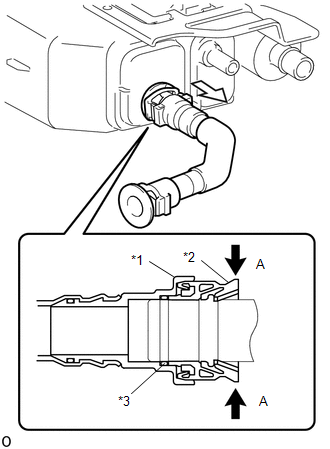
(b) Pinch portion A to disconnect the fuel tank vent hose as shown in the illustration.
NOTICE:
- Remove any dirt and foreign objects from the fuel tank vent hose connector before performing the work.
- Do not allow any scratches or foreign objects on the parts when disconnecting, as the fuel tank vent hose connector has the O-ring that seals the pipe.
- Perform the work by hand. Do not use any tools.
- Do not forcibly bend, twist or turn the nylon tube.
- Protect the disconnected part by covering it with a vinyl bag after disconnecting the fuel tank vent hose.
- If the fuel tank vent hose connector and pipe are stuck, push and pull them to release.
|
*1 |
Fuel Tank Vent Hose Retainer |
|
*2 |
Fuel Tank Vent Hose Connector |
|
*3 |
O-ring |
|
|
Pinch |
.png) |
Pull |
4. REMOVE CHARCOAL CANISTER ASSEMBLY
|
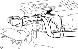
(a) Disconnect the 3 connectors. |
|
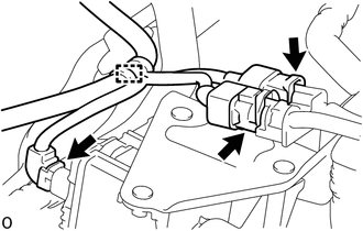
(b) Disengage the clamp to separate the wire harness.
|
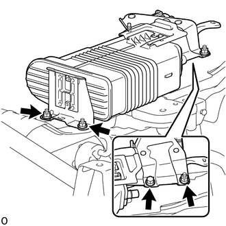
(c) Remove the nut. |
|
(d) Disengage the guide to separate the wire harness bracket.
|
(e) Remove the bolt, 3 nuts and charcoal canister assembly. |
|
5. DISCONNECT FUEL TANK VENT HOSE SUB-ASSEMBLY
(a) Push the fuel tank vent hose sub-assembly deep inside.
|
|
Push |
(b) Pinch portion A to disconnect the fuel tank vent hose sub- assembly as shown in the illustration.
NOTICE:
- Remove any dirt and foreign objects from the fuel tank vent hose sub-assembly connector before performing the work.
- Do not allow any scratches or foreign objects on the parts when disconnecting, as the fuel tank vent hose sub-assembly connector has the O-ring that seals the pipe.
- Perform the work by hand. Do not use any tools.
- Do not forcibly bend, twist or turn the nylon tube.
- Protect the disconnected part by covering it with a vinyl bag after disconnecting the fuel tank vent hose sub-assembly.
- If the fuel tank vent hose sub-assembly connector and pipe are stuck, push and pull them to release.
|
*1 |
Fuel Tank Vent Hose Retainer |
|
*2 |
Fuel Tank Vent Hose Connector |
|
*3 |
O-ring |
|
|
Pinch |
|
|
Pull |
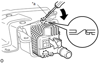
6. REMOVE CHARCOAL CANISTER LEAK DETECTION PUMP SUB-ASSEMBLY
(a) Before removing the leak detection pump sub-assembly, clean the canister by blowing air into it to ensure that the canister is free of foreign matter.
NOTICE:
- Make sure to clean the canister using only air.
- Do not use gasoline, thinners or solvents.
|
(b) Using a screwdriver with its tip wrapped in protective tape, disengage the 2 claws to remove the charcoal canister leak detection pump sub-assembly as shown in the illustration. |
|
(c) Check if the charcoal canister assembly contains foreign matter such as mud or water.
(1) Visually check that the inside of the charcoal canister assembly is free of foreign matter.
(2) Hold the charcoal canister assembly upside down to make sure that the charcoal canister assembly is free of foreign matter. If the charcoal canister assembly contains foreign matter, replace the charcoal canister assembly.
 Components
COMPONENTS
ILLUSTRATION
*1
CHARCOAL CANISTER ASSEMBLY
*2
CHARCOAL CANISTER FUEL HOSE
*3
CHARCOAL CANISTER LEAK DETECTION PUM ...
 Inspection
INSPECTION
PROCEDURE
1. INSPECT CHARCOAL CANISTER ASSEMBLY
(a) Visually check the charcoal canister assembly.
(1) Visually check the charcoal canister assembly for cracks or damage.
...
Other materials:
Problem Symptoms Table
PROBLEM SYMPTOMS TABLE
HINT:
Use the table below to help determine the cause of problem symptoms.
If multiple suspected areas are listed, the potential causes of the symptoms
are listed in order of probability in the "Suspected Area" column of the
table. Check each sy ...
On-vehicle Inspection
ON-VEHICLE INSPECTION
PROCEDURE
1. INSPECT SIDE AIRBAG SENSOR ASSEMBLY (for Vehicle not Involved in Collision)
(a) Perform a Diagnostic System Check (See page
).
2. INSPECT SIDE AIRBAG SENSOR ASSEMBLY (for Vehicle Involved in Collision and
Airbag has not Deployed)
CAUTION:
For side airbag ...
Inspection
INSPECTION
PROCEDURE
1. INSPECT FUEL PUMP
(a) Inspect the resistance of the fuel pump.
(1) Measure the resistance according to the value(s) in the table below.
Text in Illustration
*a
Component without harness connected
(Fuel Pump)
...
