Toyota Tacoma (2015-2018) Service Manual: Inspection
INSPECTION
PROCEDURE
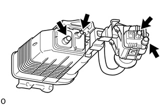
1. INSPECT CHARCOAL CANISTER ASSEMBLY
|
(a) Visually check the charcoal canister assembly. (1) Visually check the charcoal canister assembly for cracks or damage. If cracks or damage are found, replace the charcoal canister assembly. |
|
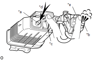
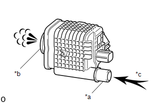
(b) Check charcoal canister assembly operation.
|
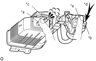
*a |
Vent Port |
|
*b |
Air Inlet Port |
|
*c |
Purge Port |
|
*d |
Air |
|
*e |
Leak Detection Pump Sub-assembly Connector |
(1) With the purge port and leak detection pump sub-assembly connector closed, blow 5 kPa (0.05 kgf/cm2, 0.7 psi) of air into the vent port, and check that air flows from the air inlet port.
If the result is not as specified, replace the charcoal canister assembly.
|
(2) With the vent port and leak detection pump sub-assembly connector closed, blow 5 kPa (0.05 kgf/cm2, 0.7 psi) of air into the air inlet port, and check that air flows from the purge port. If the result is not as specified, replace the charcoal canister assembly. |
|
|
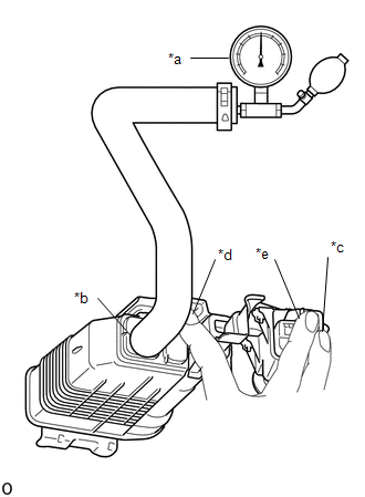
(c) Check for air leaks. (1) Connect a pressure gauge to the vent port of the charcoal canister. (2) With the purge port, air inlet port and leak detection pump sub-assembly connector closed, apply 20 kPa (150 mmHg, 5.91 in.Hg) of pressurized air into the vent port, then confirm that pressure is retained for 1 minute. If the result is not as specified, replace the charcoal canister assembly. |
|
2. INSPECT CHARCOAL CANISTER LEAK DETECTION PUMP SUB-ASSEMBLY
(a) Check the charcoal canister leak detection pump sub-assembly.
|
*a |
Port A |
|
*b |
Port B |
|
*c |
Air |
(1) Check that air flows from port A to port B.
If the result is not as specified, replace the charcoal canister leak detection pump sub-assembly.
|
(2) Connect the positive (+) lead of the battery to terminal 5 and the negative (-) lead to terminal 1. |
|
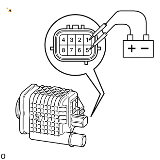
(3) Check that a clicking sound is heard from the leak detection pump sub-assembly.
If the result is not as specified, replace the charcoal canister leak detection pump sub-assembly.
 Removal
REMOVAL
PROCEDURE
1. REMOVE FUEL TANK ASSEMBLY
Click here
2. DISCONNECT CHARCOAL CANISTER FUEL HOSE
(a) Loosen the hose clip and disconnect the charcoal canister fuel hose.
...
 Installation
INSTALLATION
PROCEDURE
1. INSTALL CHARCOAL CANISTER LEAK DETECTION PUMP SUB-ASSEMBLY
(a) Engage the 2 claws to install a new charcoal canister leak detection
pump sub-assembly to the ...
Other materials:
Installation
INSTALLATION
PROCEDURE
1. INSTALL REAR DIFFERENTIAL DRIVE PINION BEARING SPACER
(a) Install a new front differential drive pinion bearing spacer.
HINT:
Make sure the front differential drive pinion bearing spacer is installed correctly.
2. INSTALL DIFFERENTIAL OIL STORAGE RING
(a) Using a bra ...
Reassembly
REASSEMBLY
CAUTION / NOTICE / HINT
CAUTION:
Wear protective gloves. Sharp areas on the parts may injure your hands.
PROCEDURE
1. INSTALL SEPARATE TYPE REAR SEATBACK COVER
(a) Using hog ring pliers, install the separate type rear seatback cover
with 2 new hog rings.
Text in Il ...
Sound Quality is Bad Only when CD is Played (Volume is Too Low)
PROCEDURE
1.
REPLACE CD AND RECHECK
(a) Replace the CD with a known good one and recheck.
(1) Check if the same malfunction occurs again.
OK:
Malfunction disappears.
OK
END
NG
REPLACE NAVIGATION RECEIVER ASSEMBLY ...
