Toyota Tacoma (2015-2018) Service Manual: Removal
REMOVAL
PROCEDURE
1. REMOVE STEERING PAD
(See page .gif) )
)
2. REMOVE STEERING WHEEL ASSEMBLY
3. REMOVE LOWER STEERING COLUMN COVER
4. REMOVE UPPER STEERING COLUMN COVER
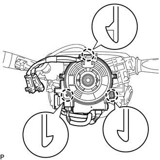
5. REMOVE SPIRAL CABLE SUB-ASSEMBLY WITH SENSOR
|
(a) Slide the slider and disconnect the airbag connector. |
|
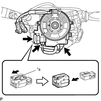
(b) Disconnect the 2 connectors from the spiral cable sub-assembly with sensor.
Text in Illustration|
*a |
Slider |
NOTICE:
When handling the airbag connector, take care not to damage the airbag wire harness.
|
(c) Disengage the 3 claws to remove the spiral cable sub-assembly with sensor. NOTICE:
|
|
 Installation
INSTALLATION
PROCEDURE
1. INSTALL SPIRAL CABLE SUB-ASSEMBLY WITH SENSOR
(a) Check that the ignition switch is off.
(b) Check that the battery n ...
 Traction Off Switch
Components
COMPONENTS
ILLUSTRATION
Removal
REMOVAL
PROCEDURE
1. REMOVE ROOF CONSOLE BOX ASSEMBLY
(See page )
2. REMOVE A-TRAC SWITCH (TRACTION CONTROL SWITCH)
(a) Disconnect the A-TRAC ...
Other materials:
System Description
SYSTEM DESCRIPTION
1. OUTLINE OF THEFT DETERRENT SYSTEM
The theft deterrent system can be set/canceled by locking/unlocking
the doors using the following operation:
Entry lock operation*1
Wireless lock operation*2
Key-linked lock operation
* ...
Removal
REMOVAL
PROCEDURE
1. REMOVE RADIATOR GRILLE
(a) w/ Toyota Safety Sense P
(1) Disconnect the connector.
(2) Disengage the clamp.
(b) Put protective tape around the radiator grille.
...
Data Signal Circuit between Navigation Receiver Assembly and Extension Module
DESCRIPTION
The stereo component tuner assembly sends the sound data signal or image data
signal from a device to the navigation receiver assembly via this circuit.
WIRING DIAGRAM
CAUTION / NOTICE / HINT
NOTICE:
After replacing the stereo component tuner assembly of vehicles subscribed to
...
