Toyota Tacoma (2015-2018) Service Manual: Central Gateway ECU Communication Stop Mode
DESCRIPTION
|
Detection Item |
Symptom |
Trouble Area |
|---|---|---|
|
Central Gateway ECU Communication Stop Mode |
Communication system DTCs (DTCs that start with U) that correspond to "Central Gateway ECU Communication Stop Mode" in "DTC Combination Table" are output. Click here |
|
WIRING DIAGRAM
CAUTION / NOTICE / HINT
CAUTION:
When performing the confirmation driving pattern, obey all speed limits and traffic laws.
NOTICE:
- Because the order of diagnosis is important to allow correct diagnosis,
make sure to begin troubleshooting using How to Proceed with Troubleshooting
when CAN communication system related DTCs are output.
Click here
.gif)
- Before measuring the resistance of the CAN bus, turn the ignition switch off and leave the vehicle for 1 minute or more without operating the key or any switches, or opening or closing the doors. After that, disconnect the cable from the negative (-) battery terminal and leave the vehicle for 1 minute or more before measuring the resistance.
- After turning the ignition switch off, waiting time may be required
before disconnecting the cable from the negative (-) battery terminal. Therefore,
make sure to read the disconnecting the cable from the negative (-) battery
terminal notices before proceeding with work.
Click here
- Some parts must be initialized and set when replacing or removing and
installing parts.
Click here
- After performing repairs, perform the DTC check procedure and confirm
that the DTCs are not output again.
DTC check procedure: Turn the ignition switch to ON and wait for 1 minute or more. Then operate the suspected malfunctioning system and drive the vehicle at 60 km/h (37 mph) or more for 5 minutes or more.
- After the repair, perform the CAN bus check and check that all the ECUs
and sensors connected to the CAN communication system are displayed as normal.
Click here
- Inspect the fuses for circuits related to this system before performing the following procedure.
HINT:
- Before disconnecting related connectors for inspection, push in on each connector body to check that the connector is not loose or disconnected.
- When a connector is disconnected, check that the terminals and connector body are not cracked, deformed or corroded.
PROCEDURE
|
1. |
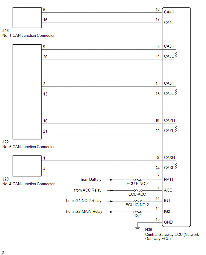
CHECK FOR OPEN IN CAN LINES (CENTRAL GATEWAY ECU (NETWORK GATEWAY ECU) CAN MAIN OR BRANCH LINE) |
|
(a) Disconnect the cable from the negative (-) battery terminal. |
|
(b) Disconnect the central gateway ECU (network gateway ECU) connector.
(c) Measure the resistance according to the value(s) in the table below.
Standard Resistance:
Bus 2|
Tester Connection |
Condition |
Specified Condition |
|---|---|---|
|
N36-18 (CA4H) - N36-17 (CA4L) |
Cable disconnected from negative (-) battery terminal |
54 to 69 Ω |
|
Tester Connection |
Condition |
Specified Condition |
|---|---|---|
|
N36-6 (CA3H) - N36-19 (CAYH) |
Cable disconnected from negative (-) battery terminal |
Below 1 Ω |
|
N36-21 (CA3L) - N36-20 (CAYL) |
Cable disconnected from negative (-) battery terminal |
Below 1 Ω |
|
Tester Connection |
Condition |
Specified Condition |
|---|---|---|
|
N36-15 (CA5H) - N36-9 (CAXH) |
Cable disconnected from negative (-) battery terminal |
Below 1 Ω |
|
N36-16 (CA5L) - N36-24 (CAXL) |
Cable disconnected from negative (-) battery terminal |
Below 1 Ω |
|
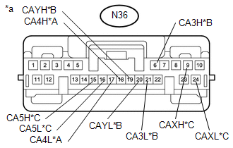
*A |
Bus 2 |
|
*B |
Bus 3 |
|
*C |
Bus 5 |
|
*a |
Front view of wire harness connector (to Central Gateway ECU (Network Gateway ECU)) |
|
Result |
Proceed to |
|---|---|
|
OK |
A |
|
NG (Bus 2 Branch Lines) |
B |
|
NG (Bus 3 or Bus 5 Main Lines) |
C |
| B | .gif) |
REPAIR OR REPLACE CAN BRANCH LINES OR CONNECTOR (CENTRAL GATEWAY ECU (NETWORK GATEWAY ECU)) |
| C | |
REPAIR OR REPLACE CAN MAIN BUS LINES OR CONNECTOR (CENTRAL GATEWAY ECU (NETWORK GATEWAY ECU)) |
|
.gif)
|
2. |
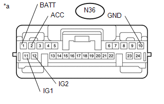
CHECK HARNESS AND CONNECTOR (POWER SOURCE CIRCUIT) |
|
(a) Measure the resistance according to the value(s) in the table below. Standard Resistance:
|
|
(b) Connect the cable to the negative (-) battery terminal.
(c) Measure the voltage according to the value(s) in the table below.
Standard Voltage:
|
Tester Connection |
Switch Condition |
Specified Condition |
|---|---|---|
|
N36-1 (BATT) - Body ground |
Always |
11 to 14 V |
|
N36-2 (ACC) - Body ground |
Ignition switch ACC |
11 to 14 V |
|
N36-11 (IG1) - Body ground |
Ignition switch IG |
11 to 14 V |
|
N36-12 (IG2) - Body ground |
Ignition switch IG |
11 to 14 V |
|
*a |
Front view of wire harness connector (to Central Gateway ECU (Network Gateway ECU)) |
| OK | |
REPLACE CENTRAL GATEWAY ECU (NETWORK GATEWAY ECU) |
| NG | |
REPAIR OR REPLACE HARNESS OR CONNECTOR |
 Radio Receiver Assembly Communication Stop Mode
DESCRIPTION
Detection Item
Symptom
Trouble Area
Radio Receiver Assembly Communication Stop Mode
Either condition is met:
Com ...
 Millimeter Wave Radar Sensor Communication Stop Mode
DESCRIPTION
Detection Item
Symptom
Trouble Area
Millimeter Wave Radar Sensor Communication Stop Mode
Either Condition is met:
...
Other materials:
Pressure Sensor or Switch (C1254)
DESCRIPTION
The accumulator pressure sensor is connected to the skid control ECU in the master
cylinder solenoid.
DTC No.
DTC Detecting Condition
Trouble Areas
C1254
Accumulator pressure sensor fault
(Fluid pressure does not chang ...
Security Indicator Light Does not Blink
DESCRIPTION
The transponder key ECU assembly blinks the security indicator light
when the immobiliser is set (no key is in the ignition key cylinder).
w/ Theft Deterrent System:
The main body ECU (multiplex network body ECU) blinks the security indicator
light when the thef ...
System Description
SYSTEM DESCRIPTION
1. SYSTEM FUNCTION
Function
Outline
Push-button start function
When the key is brought into the vehicle and verified, this function
changes the power source or starts the engine when the engine switch and
brake pedal are ...
