Toyota Tacoma (2015-2018) Service Manual: Traction Off Switch
Components
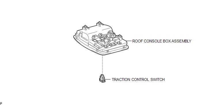
COMPONENTS
ILLUSTRATION
Removal
REMOVAL
PROCEDURE
1. REMOVE ROOF CONSOLE BOX ASSEMBLY
(See page .gif) )
)
2. REMOVE A-TRAC SWITCH (TRACTION CONTROL SWITCH)
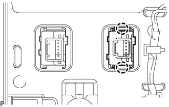
(a) Disconnect the A-TRAC switch (traction control switch) connector.
|
(b) Using a screwdriver, detach the 2 claws and remove the A-TRAC switch (traction control switch) from the roof console box assembly. |
|
Inspection
INSPECTION
PROCEDURE
1. INSPECT A-TRAC SWITCH (TRACTION CONTROL SWITCH)
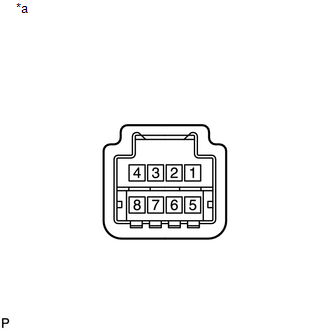
(a) Check the resistance.
|
(1) Measure the resistance according to the value(s) in the table below. Text in Illustration
Standard Resistance:
If the value is not as specified, replace the A-TRAC switch (traction control switch). |
|
Installation
INSTALLATION
PROCEDURE
1. INSTALL A-TRAC SWITCH (TRACTION CONTROL SWITCH)
(a) Attach the 2 claws to install the A-TRAC switch (traction control switch) into the roof console box assembly.
(b) Connect the A-TRAC switch (traction control switch) connector.
2. INSTALL ROOF CONSOLE BOX ASSEMBLY
(See page .gif) )
)
 Removal
REMOVAL
PROCEDURE
1. REMOVE STEERING PAD
(See page )
2. REMOVE STEERING WHEEL ASSEMBLY
3. REMOVE LOWER STEERING COLUMN COVER
4. REMOVE UPPER STEERING COLUMN COVER
5. REMOVE SPIRAL ...

Other materials:
Reassembly
REASSEMBLY
PROCEDURE
1. INSTALL SHIFT SOLENOID VALVE SLT
(a) Install the shift solenoid valve SLT and straight pin to the transmission
valve body assembly.
2. INSTALL SHIFT SOLENOID VALVE SL2
(a) Install the shift solenoid valv ...
Four-wheel drive system
Use the front-wheel drive control switch to select the following transfer modes.
H2 (high speed position, two-wheel
drive)
Use this for normal driving on dry hard-surfaced roads.
This position gives greater economy, quietest ride and least wear.
H4 (high speed position, four-wheel
drive) ...
Diagnosis System
DIAGNOSIS SYSTEM
1. DESCRIPTION
The ECU stores trouble codes when malfunctions occur.
The diagnostic system allows for reading of the trouble codes from the DLC3.
Use the Techstream to help diagnose and repair the problem.
2. CHECK DLC3
(a) Check the DLC3 (See page ).
3. INSPECT BATTERY VOLT ...
