Toyota Tacoma (2015-2018) Service Manual: Disassembly
DISASSEMBLY
PROCEDURE
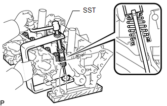
1. REMOVE INTAKE VALVE
|
(a) Using SST, compress the inner compression spring and remove the valve spring retainer locks. SST: 09202-70020 SST: 09202-00021 09202-01010 09202-01020 |
|
(b) Remove the valve spring retainer, inner compression spring and intake valve.
HINT:
Arrange the removed parts in the correct order.
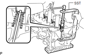
2. REMOVE EXHAUST VALVE
|
(a) Using SST, compress the inner compression spring and remove the valve spring retainer locks. SST: 09202-70020 09202-01010 09202-01020 SST: 09202-00021 |
|
(b) Remove the valve spring retainer, inner compression spring and exhaust valve.
HINT:
Arrange the removed parts in the correct order.
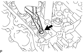
3. REMOVE VALVE STEM OIL SEAL
|
(a) Using needle-nose pliers, remove the valve stem oil seals. |
|
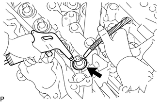
4. REMOVE VALVE SPRING SEAT
|
(a) Using compressed air and a magnet hand, remove the valve spring seats by blowing air onto them. |
|
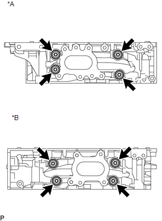
5. REMOVE NO. 1 STRAIGHT SCREW PLUG
NOTICE:
If water leaks from a straight screw plug or the plug is corroded, replace it.
|
(a) Using a 10 mm hexagon wrench, remove the 4 No. 1 straight screw plugs and 4 gaskets. Text in Illustration
|
|
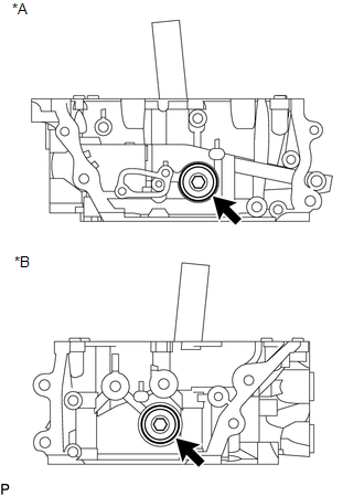
6. REMOVE NO. 2 STRAIGHT SCREW PLUG
NOTICE:
If water leaks from a straight screw plug or the plug is corroded, replace it.
|
(a) Using a 14 mm hexagon wrench, remove the 2 No. 2 straight screw plugs and 2 gaskets. Text in Illustration
|
|
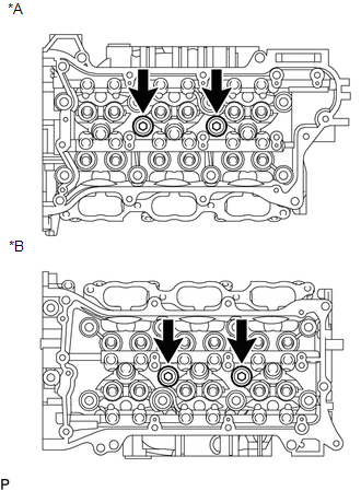
7. REMOVE NO. 3 STRAIGHT SCREW PLUG
NOTICE:
If water leaks from a straight screw plug or the plug is corroded, replace it.
|
(a) Using a 10 mm hexagon wrench, remove the 8 No. 3 straight screw plugs and 8 gaskets. Text in Illustration
|
|
8. REMOVE UNION
NOTICE:
It is not necessary to remove the union unless it is being replaced.
9. REMOVE STUD BOLT
NOTICE:
If the stud bolt is deformed or the threads are damaged, replace it.
 Precaution
PRECAUTION
HINT:
Any digits beyond the 0.01 mm (1/1000 in.) place for standard, minimum
and maximum values should be used as a reference only.
When both standard and maximum or minim ...
 Inspection
INSPECTION
PROCEDURE
1. INSPECT CYLINDER HEAD SUB-ASSEMBLY
(a) Using a precision straightedge and feeler gauge, measure the warpage of the
contact surfaces where the cylinder head contacts the cy ...
Other materials:
Open or Short in Master Cylinder Pressure Sensor (C1421,C1423,C1424,C142A,C1449)
DESCRIPTION
DTC No.
Detection Item
DTC Detection Condition
Trouble Area
C1421
Open or Short in Master Cylinder Pressure Sensor
Any of the following is detected:
When voltage at terminal +BS is 9.5 V or ...
System Diagram
SYSTEM DIAGRAM
...
Lost Communication with Alternator Missing Message (P161A87)
DESCRIPTION
The ECM communicates with the generator assembly via LIN communication. If a
LIN communication error is detected, the ECM stores this DTC.
DTC No.
DTC Detection Condition
Trouble Area
P161A87
Generator assembly or ECM commu ...
