Toyota Tacoma (2015-2018) Service Manual: Removal
REMOVAL
PROCEDURE
1. REMOVE LOWER INSTRUMENT PANEL FINISH PANEL SUB-ASSEMBLY RH
(See page .gif) )
)
2. REMOVE LOWER INSTRUMENT PANEL ASSEMBLY
(See page )
3. REMOVE AIR CONDITIONING CONTROL ASSEMBLY
(a) for Automatic Air Conditioning System (See page
)
(b) for Manual Air Conditioning System (See page
)
4. REMOVE FRONT CONSOLE BOX
(See page )
5. REMOVE NO. 2 INSTRUMENT PANEL GARNISH SUB-ASSEMBLY
(See page )
6. REMOVE INSTRUMENT PANEL LOWER CENTER FINISH PANEL
(See page )
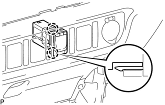
7. REMOVE NO. 1 STEREO JACK ADAPTER ASSEMBLY
|
(a) Disengage the 2 claws to remove the No. 1 stereo jack adapter assembly. |
|
 Components
COMPONENTS
ILLUSTRATION
...
 Installation
INSTALLATION
PROCEDURE
1. INSTALL NO. 1 STEREO JACK ADAPTER ASSEMBLY
(a) Engage the 2 claws to install the No. 1 stereo jack adapter assembly.
2. INSTALL INSTRUMENT PANEL LOWER CENTER FINISH PANEL ...
Other materials:
Horn Relay
On-vehicle Inspection
ON-VEHICLE INSPECTION
PROCEDURE
1. INSPECT HORN RELAY ASSEMBLY
(a) Check the resistance.
(1) Measure the resistance according to the value(s) in the table below.
Standard Resistance:
Tester Connection
Connection
...
Precaution
PRECAUTION
1. IGNITION SWITCH EXPRESSIONS
(a) The type of ignition switch used on this model differs according to the specifications
of the vehicle. The expressions listed in the table below are used in this section.
Expression
Ignition Switch (Position)
Engine ...
Components
COMPONENTS
ILLUSTRATION
HINT:
The following specifications are for BD22A (w/o Differential Lock). BD22A differentials
are equipped with M10 rear differential carrier to rear axel housing fasteners.
ILLUSTRATION
ILLUSTRATION
...
