Toyota Tacoma (2015-2018) Service Manual: Components
COMPONENTS
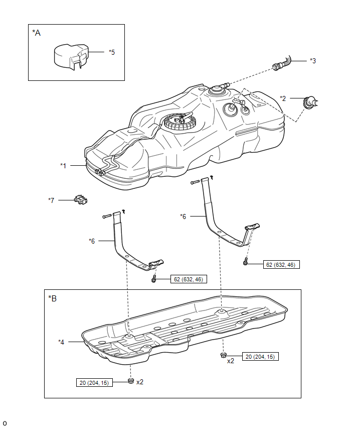
ILLUSTRATION
|
*A |
w/ Fuel Tank Cover |
*B |
for Hydraulic Brake Booster |
|
*1 |
FUEL TANK ASSEMBLY |
*2 |
FUEL TANK INLET PIPE SUB-ASSEMBLY |
|
*3 |
FUEL TANK VENT HOSE SUB-ASSEMBLY |
*4 |
NO. 1 FUEL TANK PROTECTOR SUB-ASSEMBLY |
|
*5 |
FUEL TANK COVER |
*6 |
FUEL TANK BAND |
|
*7 |
FUEL PIPE CLAMP |
- |
- |
.png) |
N*m (kgf*cm, ft.*lbf): Specified torque |
- |
- |
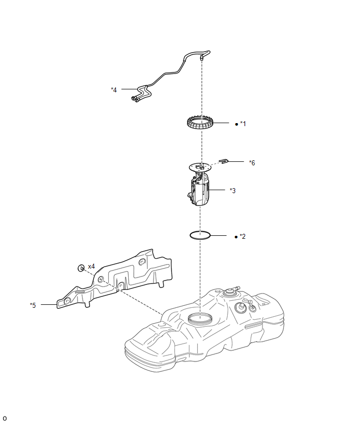
ILLUSTRATION
|
*1 |
FUEL PUMP GAUGE RETAINER |
*2 |
FUEL SUCTION TUBE SET GASKET |
|
*3 |
FUEL SUCTION TUBE WITH PUMP AND GAUGE ASSEMBLY |
*4 |
FUEL TANK MAIN TUBE SUB-ASSEMBLY |
|
*5 |
NO. 1 FUEL TANK PROTECTOR |
*6 |
TUBE JOINT CLIP |
|
â—Ź |
Non-reusable part |
- |
- |
 Fuel Tank
...
 Removal
REMOVAL
PROCEDURE
1. PRECAUTION
NOTICE:
After turning the ignition switch off, waiting time may be required before disconnecting
the cable from the battery terminal. Therefore, make sure to read ...
Other materials:
Radar Cruise Control Presence Determination Malfunction (Engine / HV) (C1A52)
DESCRIPTION
DTC C1A52 is stored when the ECM cannot recognize the millimeter wave radar sensor
assembly.
DTC No.
Detection Item
DTC Detection Condition
Trouble Area
MIL
C1A52
Radar Cruise Control Presence Determin ...
Installation
INSTALLATION
CAUTION / NOTICE / HINT
HINT:
Perform "Inspection After Repairs" after replacing the fuel injector assembly
(See page ).
PROCEDURE
1. INSTALL FUEL INJECTOR SEAL
(a) Apply engine conditioner to the fuel injector assembly area shown
in the illustration. U ...
Installation
INSTALLATION
PROCEDURE
1. INSTALL REAR DOOR GLASS SUB-ASSEMBLY
(a) Clean and shape the contact surface of the vehicle body.
Text in Illustration
*a
Adhesive
*b
Vehicle Body
(1) Using a ...
