Toyota Tacoma (2015-2018) Service Manual: Removal
REMOVAL
PROCEDURE
1. PRECAUTION
CAUTION:
Be sure to read Precaution thoroughly before servicing (See page
.gif) ).
).
NOTICE:
After turning the ignition switch off, waiting time may be required before disconnecting the cable from the negative (-) battery terminal. Therefore, make sure to read the disconnecting the cable from the negative (-) battery terminal notices before proceeding with work.
Click here
2. DISCONNECT CABLE FROM NEGATIVE BATTERY TERMINAL
CAUTION:
Wait at least 90 seconds after disconnecting the cable from the negative (-) battery terminal to disable the SRS system.
NOTICE:
When disconnecting the cable, some systems need to be initialized after the cable is reconnected.
Click here
3. REMOVE FRONT SEAT ASSEMBLY RH
Click here
4. REMOVE OCCUPANT DETECTION ECU
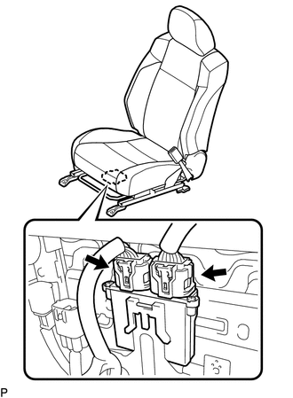
(a) Disconnect the 2 connectors from the occupant detection ECU.
|
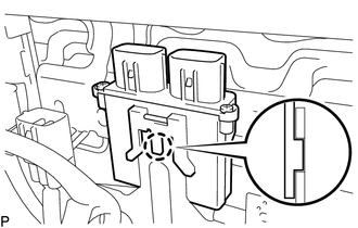
(b) Disengage the claw to remove the occupant detection ECU. |
|
 On-vehicle Inspection
ON-VEHICLE INSPECTION
PROCEDURE
1. INSPECT OCCUPANT DETECTION ECU (for Vehicle not Involved in Collision)
(a) Perform a diagnostic system check (See page
).
2. INSPECT OCCUPANT DETECTION ECU (fo ...
 Installation
INSTALLATION
PROCEDURE
1. INSTALL OCCUPANT DETECTION ECU
(a) Check that the ignition switch is OFF.
(b) Check that the cable is disconnected from the battery negative (-) terminal
is disconnecte ...
Other materials:
Steering Angle Sensor Communication Stop Mode
DESCRIPTION
Detection Item
Symptom
Trouble Area
Steering Angle Sensor Communication Stop Mode
Either condition is met:
Communication stop for "Spiral cable (Steering Angle Sensor)"
is indicated on the "C ...
Air Outlet Control Servo Motor
Inspection
INSPECTION
PROCEDURE
1. INSPECT MODE CONTROL SERVO MOTOR
(a) Inspect the servo motor operation.
(1) When 12V is applied between terminals 4 (IGN) and 1 (GND), and 0V
is applied between terminals 2 (SIG) and 1 (GND), check that the line connecting
the 2 notches ...
Engine Switch Illumination Circuit
DESCRIPTION
The illuminated entry system controls the engine switch illumination.
WIRING DIAGRAM
PROCEDURE
1.
READ VALUE USING TECHSTREAM (POWER/ENGINE SW LIGHT)
(a) Connect the Techstream to the DLC3.
(b) Turn the engine switch to ON.
(c) Turn the Techstream ...
