Toyota Tacoma (2015-2018) Service Manual: Removal
REMOVAL
PROCEDURE
1. REMOVE REAR SEAT CUSHION ASSEMBLY
.gif)
2. REMOVE NO. 4 ROOM PARTITION COVER LH
3. REMOVE NO. 4 ROOM PARTITION COVER RH
4. REMOVE NO. 3 ROOM PARTITION COVER
5. REMOVE BACK PANEL GARNISH HOLE PLUG
6. REMOVE BACK PANEL TRIM
7. REMOVE FRONT DOOR SCUFF PLATE
8. REMOVE REAR DOOR SCUFF PLATE
9. DISCONNECT FRONT DOOR OPENING TRIM WEATHERSTRIP
|
(a) Disconnect the front door opening trim weatherstrip to the extent which allows the removal of the roof side garnish inner, quarter trim lower panel and quarter inside trim board. |
|
10. REMOVE ROOF SIDE INNER GARNISH CAP
11. REMOVE ROOF SIDE INNER GARNISH
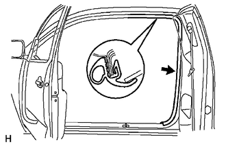
12. DISCONNECT REAR SEAT 3 POINT TYPE OUTER BELT ASSEMBLY
13. REMOVE QUARTER TRIM LOWER PANEL
14. REMOVE QUARTER INSIDE TRIM BOARD
15. REMOVE REAR SEAT 3 POINT TYPE OUTER BELT ASSEMBLY
|
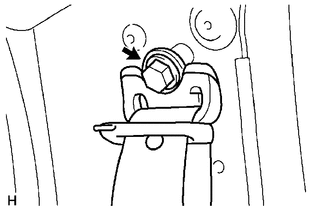
(a) Loosen the bolt to disconnect the shoulder anchor. |
|
|
(b) Remove the bolt. |
|
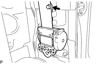
(c) Disengage the 2 guides to remove the rear seat 3 point type outer belt assembly.
 Installation
INSTALLATION
PROCEDURE
1. INSTALL REAR SEAT 3 POINT TYPE OUTER BELT ASSEMBLY
(a) Before installing the rear seat 3 point type outer belt assembly,
check the ELR function.
Text in ...

Other materials:
Front Right Seat Heat Sensor Circuit (B14C0)
DESCRIPTION
Output to the front seat cushion heater assembly RH temperature sensor stops
if one of the following occurs: 1) the temperature sensor is open or shorted; or
2) the temperature sensor is damaged and its output value does not change.
DTC Code
DTC Detection Cond ...
Inspection
INSPECTION
PROCEDURE
1. INSPECT TRANSMISSION WIRE
(a) Measure the resistance according to the value(s) in the table below.
Text in Illustration
*a
Component without harness connected
(Transmission Wire)
Standard Resistance: ...
Front Radar Sensor Incorrect Axial Gap (C1A11)
DESCRIPTION
When the vehicle is determined to be driving in a straight line or on a gradual
curve based on signals from the yaw rate sensor, etc., the millimeter wave radar
sensor assembly performs self diagnosis to check if the sensor beam axis has deviated.
If the millimeter wave radar sens ...
