Toyota Tacoma (2015-2018) Service Manual: Installation
INSTALLATION
PROCEDURE
1. INSTALL REAR SEAT 3 POINT TYPE OUTER BELT ASSEMBLY
|
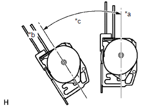
(a) Before installing the rear seat 3 point type outer belt assembly, check the ELR function. Text in Illustration
(1) When the inclination of the retractor is 15° or less, check that the belt can be pulled from the retractor. When the inclination of the retractor is over 45°, check that the belt locks. NOTICE: Do not disassemble the retractor. If operation is not as specified, replace the rear seat 3 point type outer belt assembly. |
|
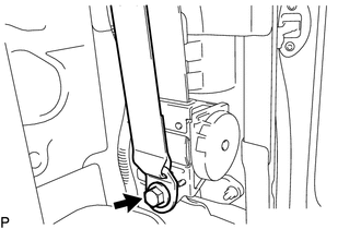
(b) Engage the 2 guides to install the rear seat 3 point type outer belt assembly with the bolt.
Torque:
12.5 N·m {127 kgf·cm, 9 ft·lbf}
(c) Tighten the bolt to connect the shoulder anchor.
Torque:
42 N·m {428 kgf·cm, 31 ft·lbf}
(d) Check that the shoulder anchor rotates smoothly.
|
(e) Connect the floor anchor with the bolt. Torque: 42 N·m {428 kgf·cm, 31 ft·lbf} |
|
(f) Check the ELR lock.
NOTICE:
The check should be performed with the rear seat 3 point type outer belt assembly installed.
(1) With the belt installed, check that the belt locks when it is pulled out quickly.
If the operation is not as specified, replace the rear seat 3 point type outer belt assembly.
(g) Remove the bolt to disconnect the floor anchor.
2. INSTALL QUARTER INSIDE TRIM BOARD
.gif)
3. CONNECT REAR SEAT 3 POINT TYPE OUTER BELT ASSEMBLY
4. INSTALL QUARTER TRIM LOWER PANEL
5. INSTALL ROOF SIDE INNER GARNISH
6. INSTALL ROOF SIDE INNER GARNISH CAP
7. CONNECT FRONT DOOR OPENING TRIM WEATHERSTRIP
8. INSTALL REAR DOOR SCUFF PLATE
9. INSTALL FRONT DOOR SCUFF PLATE
10. INSTALL BACK PANEL TRIM
11. INSTALL NO. 3 ROOM PARTITION COVER
12. INSTALL NO. 4 ROOM PARTITION COVER LH
13. INSTALL NO. 4 ROOM PARTITION COVER RH
14. INSTALL BACK PANEL GARNISH HOLE PLUG
15. INSTALL REAR SEAT CUSHION ASSEMBLY
 Components
COMPONENTS
ILLUSTRATION
ILLUSTRATION
...
 Removal
REMOVAL
PROCEDURE
1. REMOVE REAR SEAT CUSHION ASSEMBLY
2. REMOVE NO. 4 ROOM PARTITION COVER LH
3. REMOVE NO. 4 ROOM PARTITION COVER RH
4. REMOVE NO. 3 ROOM PARTITION COVER
5. REMO ...
Other materials:
Driver Side Door Entry Lock and Unlock Functions do not Operate
DESCRIPTION
If the entry lock and unlock functions do not operate for the driver door only,
the request code may not be being transmitted from the driver door or the front
door outside handle assembly LH (touch sensor) may be malfunctioning. If the entry
functions for other doors operate prop ...
How To Proceed With Troubleshooting
CAUTION / NOTICE / HINT
HINT:
Use the following procedure to troubleshoot the navigation system.
*: Use the Techstream.
PROCEDURE
1.
VEHICLE BROUGHT TO WORKSHOP
NEXT
2 ...
Sliding Roof ECU Communication Stop (B1273)
DESCRIPTION
This DTC is stored when LIN communication between the sliding roof ECU (sliding
roof drive gear sub-assembly) and main body ECU (multiplex network body ECU) stops
for 10 seconds or more.
DTC No.
DTC Detection Condition
Trouble Area
...
