Toyota Tacoma (2015-2018) Service Manual: Components
COMPONENTS
ILLUSTRATION
ILLUSTRATION
ILLUSTRATION

 Removal
REMOVAL
PROCEDURE
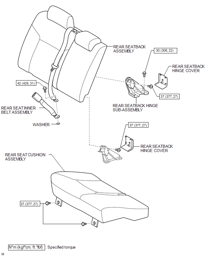
1. REMOVE REAR SEAT CUSHION ASSEMBLY
(a) Remove the 2 bolts and rear seat cushion assembly.
2. REMOVE REAR SEATBACK HINGE COV ...
Other materials:
Installation
INSTALLATION
PROCEDURE
1. INSTALL REAR BRAKE DRUM SUB-ASSEMBLY
(a) Install a new drum gasket onto the rear brake drum.
(b) Install the rear brake drum.
2. ADJUST REAR DRUM BRAKE SHOE CLEARANCE
(a) Provisionally install the hub nuts.
(b) Remove the hole plug, and turn the adjuster to expand ...
Removal
REMOVAL
CAUTION / NOTICE / HINT
HINT:
Use the same procedure for both the LH and RH sides.
The procedure described below is for the LH side.
PROCEDURE
1. REMOVE FRONT NO. 1 WHEEL OPENING EXTENSION PAD
Click here
2. SEPARATE FRONT FENDER LINER
(a) Remove the 2 ...
System Description
SYSTEM DESCRIPTION
1. UNLOCK OPERATION CONDITIONS FOR STEERING LOCK
(a) When the following condition is met, the unlock operation is performed.
The engine switch is on (ACC) or on (IG).
HINT:
When the engine switch is turned on (ACC) or on (IG) and the key and
certification ECU ( ...
