Toyota Tacoma (2015-2018) Service Manual: Removal
REMOVAL
PROCEDURE
1. REMOVE SHIFT LEVER KNOB SUB-ASSEMBLY (for Automatic Transmission)
|
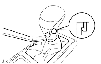
(a) Using a molding remover A, disengage the 2 claws to separate the shifting hole cover sub-assembly. |
|
|
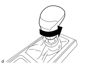
(b) Rotate the shift lever knob sub-assembly as shown in the illustration to remove it. |
|
2. REMOVE SHIFT LEVER KNOB SUB-ASSEMBLY (for Manual Transmission)
|
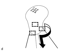
(a) Engage the 3 guides to separate the shifting hole cover sub-assembly as shown in the illustration. |
|
|
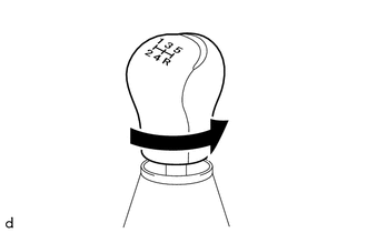
(b) Rotate the shift lever knob sub-assembly as shown in the illustration to remove it. |
|
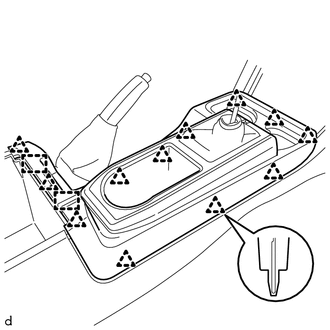
3. REMOVE CONSOLE UPPER PANEL SUB-ASSEMBLY (for Automatic Transmission)
|
(a) Disengage the 12 clips and 2 guides to remove the console upper panel sub-assembly. |
|
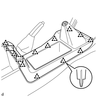
4. REMOVE CONSOLE UPPER PANEL SUB-ASSEMBLY (for Manual Transmission)
|
(a) Disengage the 12 clips and 2 guides to remove the console upper panel sub-assembly. |
|
5. REMOVE CONSOLE BOX CARPET
|
(a) Remove the console box carpet. |
|
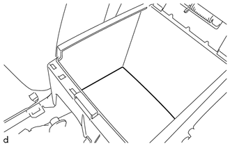
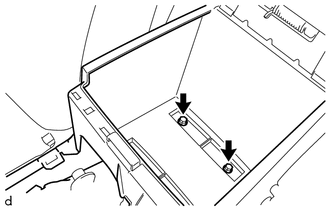
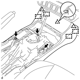
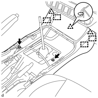
6. REMOVE REAR CONSOLE BOX ASSEMBLY
|
(a) Remove the 2 bolts. |
|
|
(b) Disconnect the connector and disengage the clamp. |
|
|
(c) Disengage the 2 claws and 4 guides to remove the rear console box assembly. |
|
7. REMOVE FRONT CONSOLE BOX (for Automatic Transmission)
(a) w/ Wireless Charger:
(1) Disconnect the connector.
|
(b) Remove the 3 screws. |
|
(c) Disengage the 3 clips and 4 guides to remove the front console box.
8. REMOVE FRONT CONSOLE BOX (for Manual Transmission)
(a) w/ Wireless Charger:
(1) Disconnect the connector.
|
(b) Remove the 2 screws. |
|
(c) Disengage the 3 clips and 4 guides to remove the front console box.
 Disassembly
DISASSEMBLY
PROCEDURE
1. REMOVE CONSOLE COMPARTMENT DOOR CUSHION
HINT:
Use the same procedure as for the opposite side.
(a) Disengage the claw to remove the console compartment door cu ...
 Installation
INSTALLATION
PROCEDURE
1. INSTALL FRONT CONSOLE BOX (for Automatic Transmission)
(a) When installing a new front console box:
Text in Illustration
*a
...
Other materials:
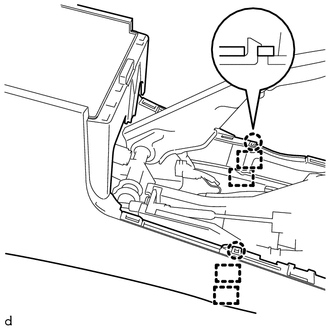
Rear Center Seat Outer Belt Assembly(for Double Cab)
Components
COMPONENTS
ILLUSTRATION
Removal
REMOVAL
PROCEDURE
1. REMOVE REAR SEATBACK HINGE COVER
2. REMOVE REAR SEATBACK BOARD SUB-ASSEMBLY
3. REMOVE SEAT BELT ANCHOR COVER CAP
4. REMOVE REAR SEAT SHOULDER BELT COVER
5. REMOVE CENTER SEATBACK PAD
(a) Remove th ...
Tire Pressure Monitor ECU Communication Stop Mode
DESCRIPTION
Detection Item
Symptom
Trouble Area
Tire Pressure Monitor ECU Communication Stop Mode
Either condition is met:
Communication stop for "Tire Pressure2" is indicated on the
"Communication Bus C ...
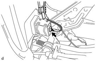
Front Speed Sensor
Removal
REMOVAL
PROCEDURE
1. PRECAUTION
NOTICE:
After turning the ignition switch off, waiting time may be required before disconnecting
the cable from the negative (-) battery terminal.
Therefore, make sure to read the disconnecting the cable from the negative (-)
battery terminal notic ...
