Toyota Tacoma (2015-2018) Service Manual: Front Speed Sensor
Removal
REMOVAL
PROCEDURE
1. PRECAUTION
NOTICE:
After turning the ignition switch off, waiting time may be required before disconnecting the cable from the negative (-) battery terminal.
Therefore, make sure to read the disconnecting the cable from the negative (-) battery terminal notices before proceeding with work.
Click here .gif)
2. DISCONNECT CABLE FROM NEGATIVE BATTERY TERMINAL
NOTICE:
When disconnecting the cable, some systems need to be initialized after the cable is reconnected.
Click here
3. REMOVE FRONT WHEEL
4. REMOVE FRONT SPEED SENSOR
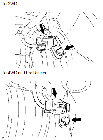
(a) Disconnect the speed sensor connector.
(b) Remove the bolt and front speed sensor.
NOTICE:
- Do not attach any foreign matter to the sensor tip.
- Ensure that no foreign matter enters the sensor installation part.
Installation
INSTALLATION
PROCEDURE
1. INSTALL FRONT SPEED SENSOR
(a) Install the front speed sensor with the bolt.
Torque:
8.3 N·m {85 kgf·cm, 73 in·lbf}
NOTICE:
Make sure that the sensor tip is clean.
(b) Connect the speed sensor connector.
2. INSTALL FRONT WHEEL
Torque:
113 N·m {1152 kgf·cm, 83 ft·lbf}
3. CONNECT CABLE TO NEGATIVE BATTERY TERMINAL
Torque:
5.4 N·m {55 kgf·cm, 48 in·lbf}
NOTICE:
When disconnecting the cable, some systems need to be initialized after the cable is reconnected.
Click here .gif)
4. CHECK VSC SENSOR SIGNAL (for Hydraulic Brake Booster)
Click here
5. CHECK VSC SENSOR SIGNAL (for Vacuum Brake Booster)
Click here
 Crawl Switch
Components
COMPONENTS
ILLUSTRATION
Inspection
INSPECTION
PROCEDURE
1. INSPECT CRAWL CONTROL SWITCH (DRIVE MONITOR SWITCH)
(a) Check the resistance.
(1) Measure the resistance according t ...
 Multi-terrain Select Switch
Components
COMPONENTS
ILLUSTRATION
Removal
REMOVAL
PROCEDURE
1. REMOVE MULTI-TERRAIN SELECT SWITCH (DRIVE MONITOR SWITCH)
(a) Disengage the 2 claws to remove the multi-terrain ...
Other materials:
System Description
SYSTEM DESCRIPTION
LANE DEPARTURE ALERT SYSTEM DESCRIPTION
(a) The lane departure alert system is a system which uses the forward recognition
camera to recognize and determine the lane and the position of the vehicle when
the vehicle is being driven on highways and other roads with white (yell ...
Installation
INSTALLATION
PROCEDURE
1. INSTALL HAZARD WARNING SIGNAL SWITCH ASSEMBLY (AIR CONDITIONING CONTROL ASSEMBLY)
(for Automatic Air Conditioning System)
(a) Connect the connectors.
(b) Engage the 8 clips to hazard warning signal switch assembly (air conditioning
control assembly).
2. INSTALL HAZ ...
Removal
REMOVAL
PROCEDURE
1. REMOVE ROOF HEADLINING ASSEMBLY (for LED Type Stop Light)
for Double Cab:
(See page
)
for Access Cab:
(See page
)
2. REMOVE CENTER STOP LIGHT ASSEMBLY (for Bulb Type Stop Light)
(a) Apply protective tape around the center stop light as ...
