Toyota Tacoma (2015-2018) Service Manual: Disassembly
DISASSEMBLY
PROCEDURE
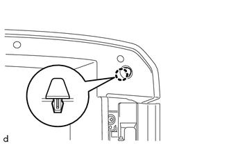
1. REMOVE CONSOLE COMPARTMENT DOOR CUSHION
HINT:
Use the same procedure as for the opposite side.
|
(a) Disengage the claw to remove the console compartment door cushion. |
|
2. REMOVE CONSOLE COMPARTMENT DOOR SUB-ASSEMBLY
|
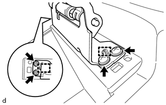
(a) Remove the 2 screws. |
|
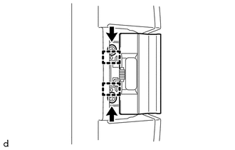
(b) Disengage the 2 guides to remove the console compartment door lock lever.
|
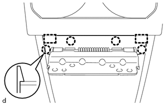
(c) Remove the 6 screws. Text in Illustration
|
|
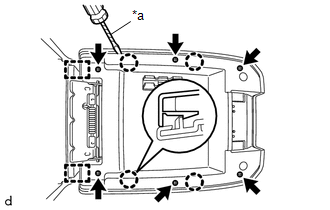
(d) Using a screwdriver with its tip wrapped in protective tape, disengage the 4 claws and 2 guides to remove the console compartment door sub-assembly.
3. REMOVE CONSOLE COMPARTMENT OUTER DOOR
|
(a) Remove the 4 screws. |
|
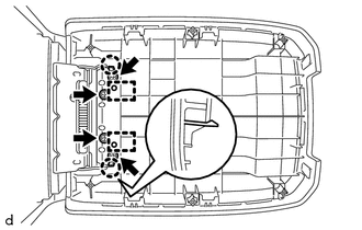
(b) Disengage the 2 claws and 2 guides to remove the console compartment outer door.
4. REMOVE CONSOLE COMPARTMENT DOOR HINGE SUB-ASSEMBLY
|
(a) Disengage the 4 claws and 2 guides to remove the console compartment door moulding cover. |
|
|
(b) Remove the 4 screws. |
|
(c) Disengage the 2 guides to remove the console compartment door hinge sub-assembly.
 Components
COMPONENTS
ILLUSTRATION
ILLUSTRATION
...
 Removal
REMOVAL
PROCEDURE
1. REMOVE SHIFT LEVER KNOB SUB-ASSEMBLY (for Automatic Transmission)
(a) Using a molding remover A, disengage the 2 claws to separate the
shifting hole cover sub-as ...
Other materials:
Steering Pad Switch
Components
COMPONENTS
ILLUSTRATION
*1
STEERING PAD SWITCH ASSEMBLY
-
-
Removal
REMOVAL
PROCEDURE
1. REMOVE STEERING PAD
(See page )
2. REMOVE STEERING PAD SWITCH ASSEMBLY
(a) Disconnect the 2 connectors.
...
Lost Communication with ECM / PCM "A" (U0100,U0129,U0142,U0151,U0163,U023A,U1104)
DESCRIPTION
The combination meter communicates with the ECM, skid control ECU, power steering
ECU, main body ECU (multiplex network body ECU), airbag sensor assembly, navigation
receiver assembly*1, radio and display receiver assembly*2, Forward recognition
camera*3 and Millimeter wave radar ...
Maintenance data (fuel, oil level, etc.)
Dimensions
2WD models except PreRunner
*: Unladen vehicle
4WD models and PreRunner (except
Regular Cab models)
*: Unladen vehicle
*: Unladen vehicle
Vehicle capacity weight
2WD models except PreRunner
*: Installing accessories in addition to those installed at the factory increase ...
