Toyota Tacoma (2015-2018) Service Manual: Removal
REMOVAL
PROCEDURE
1. REMOVE FRONT DOOR SCUFF PLATE LH (for Double Cab)
.gif)
2. REMOVE FRONT DOOR SCUFF PLATE LH (for Access Cab)
3. REMOVE COWL SIDE TRIM BOARD LH
4. REMOVE CENTER INSTRUMENT CLUSTER CENTER FINISH PANEL SUB-ASSEMBLY
5. REMOVE INSTRUMENT CLUSTER FINISH PANEL ASSEMBLY
6. REMOVE INSTRUMENT PANEL LOWER FINISH PANEL SUB-ASSEMBLY RH
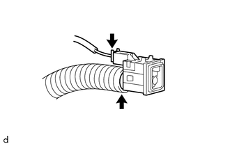
7. REMOVE COOLER (ROOM TEMPERATURE SENSOR) THERMISTOR
(a) Disengage the 2claws to disconnect the cooler (room temperature sensor) thermistor.
|
(b) Disconnect the connector. |
|
(c) Disconnect the cooler air hose to remove the cooler (room temperature sensor) thermistor.
 Inspection
INSPECTION
PROCEDURE
1. INSPECT COOLER (ROOM TEMPERATURE. SENSOR) THERMISTOR
(a) Check the resistance.
(1) Measure the resistance according to the value(s) in the table below.
Text i ...
 Installation
INSTALLATION
PROCEDURE
1. INSTALL COOLER (ROOM TEMPERATURE SENSOR) THERMISTOR
(a) Connect the cooler air hose.
(b) Connect the connector.
(c) Engage the 2 claws to connect the cooler (room temper ...
Other materials:
Dtc Check / Clear
DTC CHECK / CLEAR
NOTICE:
The steering lock ECU (steering lock actuator or UPR bracket assembly)
does not store history DTCs. If any DTCs are output, confirm and record
them as soon as possible. Do not turn the engine switch off or clear the
DTCs until the DTCs are confirmed an ...
Clutch Pedal Switch
On-vehicle Inspection
ON-VEHICLE INSPECTION
PROCEDURE
1. CHECK CLUTCH START SYSTEM
(a) Check that the engine does not start when the clutch pedal is released.
(b) Check that the engine starts when the clutch pedal is fully depressed.
If necessary, replace the clutch start switch assembly.
...
Steering Pad Switch Circuit
DESCRIPTION
This circuit sends an operation signal from the steering pad switch assembly
to the navigation receiver assembly.
If there is an open in the circuit, the audio system cannot be operated using
the steering pad switch assembly.
If there is a short in the circuit, the same condition ...
