Toyota Tacoma (2015-2018) Service Manual: Clutch Pedal Switch
On-vehicle Inspection
ON-VEHICLE INSPECTION
PROCEDURE
1. CHECK CLUTCH START SYSTEM
(a) Check that the engine does not start when the clutch pedal is released.
(b) Check that the engine starts when the clutch pedal is fully depressed.
If necessary, replace the clutch start switch assembly.
Inspection
INSPECTION
PROCEDURE
1. INSPECT CLUTCH START SWITCH ASSEMBLY
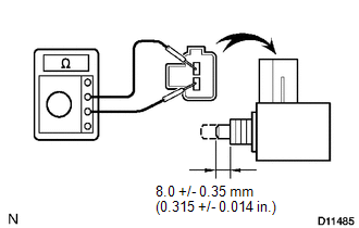
(a) Measure the resistance between the terminals when the switch is ON and OFF.
|
Switch Position |
Specified Condition |
|---|---|
|
ON (pushed) |
Below 1 Ω |
|
OFF (free) |
10 kΩ or higher |
Removal
REMOVAL
PROCEDURE
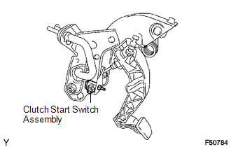
1. REMOVE CLUTCH START SWITCH ASSEMBLY
(a) Disconnect the clutch start switch assembly connector.
(b) Remove the nut and clutch start switch assembly from the clutch pedal support.
Installation
INSTALLATION
PROCEDURE
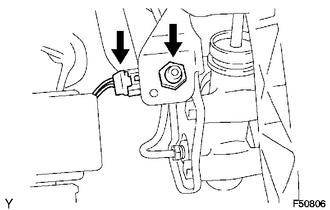
1. INSTALL CLUTCH START SWITCH ASSEMBLY
(a) Install the clutch start switch assembly with the nut.
Torque:
16 N·m {160 kgf·cm, 12 ft·lbf}
(b) Connect the clutch start switch assembly connector.
2. INSPECT CLUTCH START SWITCH ASSEMBLY
.gif)
 Installation
INSTALLATION
PROCEDURE
1. INSTALL CLUTCH PEDAL NO.1 CUSHION
(a) Install the clutch pedal No. 1 cushion to the clutch pedal sub-assembly.
2. INSTALL CLUTCH PEDAL SHAFT COLLAR
(a) Apply MP grease t ...
 Clutch Release Cylinder(for R156f)
Components
COMPONENTS
ILLUSTRATION
Removal
REMOVAL
PROCEDURE
1. DRAIN CLUTCH FLUID
2. REMOVE FRONT PROPELLER SHAFT ASSEMBLY
(See page )
3. DISCONNECT CLUTCH RELEASE CYLINDER TO FLEXIBL ...
Other materials:
Mirror Heater does not Operate with Rear Defogger Switch
DESCRIPTION
When the mirror heater switch on the air conditioning control assembly is pressed,
the operation signal is sent to the air conditioning amplifier assembly. When the
air conditioning amplifier assembly receives the signal, it turns on a relay in
the air conditioning amplifier assem ...
Installation
INSTALLATION
PROCEDURE
1. SET NO. 1 CYLINDER TO TDC/COMPRESSION
2. INSTALL CAMSHAFT TIMING GEAR BOLT
NOTICE:
There are different types of camshaft timing gear bolts. Make sure to check the
identification mark to determine the tightening torque.
*a
Identification Ma ...
Headlight Dimmer Switch Circuit
DESCRIPTION
The main body ECU (multiplex network body ECU) receives the following switch
information:
Light control switch position is off (DRL OFF), tail, head or AUTO (DRL).
Dimmer switch position is high, low or high flash (pass).
Front fog light switch position is on or off ...
