Toyota Tacoma (2015-2018) Service Manual: Steering Pad Switch Circuit
DESCRIPTION
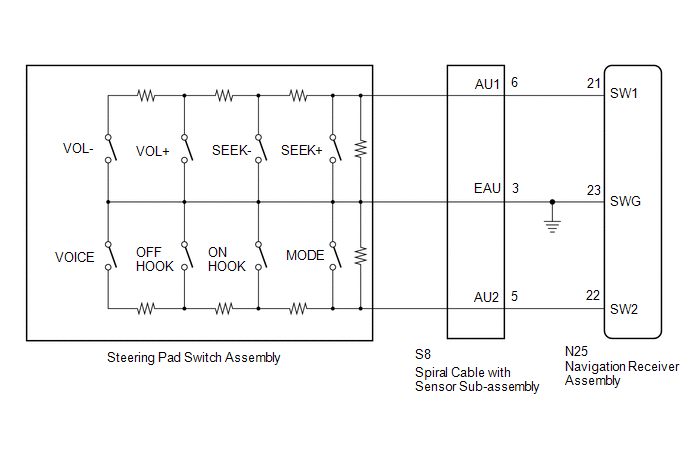
This circuit sends an operation signal from the steering pad switch assembly to the navigation receiver assembly.
If there is an open in the circuit, the audio system cannot be operated using the steering pad switch assembly.
If there is a short in the circuit, the same condition as when a switch is continuously depressed occurs.
Therefore, the navigation receiver assembly cannot be operated using the steering pad switch assembly, and also the navigation receiver assembly itself cannot function.
WIRING DIAGRAM
CAUTION / NOTICE / HINT
NOTICE:
The vehicle is equipped with a Supplemental Restraint System (SRS) which includes
components such as airbags. Before servicing (including removal or installation
of parts), be sure to read the precautionary notice for the Supplemental Restraint
System (See page .gif) ).
).
PROCEDURE
|
1. |
CHECK HARNESS AND CONNECTOR (STEERING PAD SWITCH SIGNAL) |
|
(a) Disconnect the navigation receiver assembly connector. |
|
(b) Measure the resistance according to the value(s) in the table below.
Standard Resistance:
|
Tester Connection |
Switch Condition |
Specified Condition |
|---|---|---|
|
N25-21 (SW1) - N25-23 (SWG) |
No switch is pushed |
99 to 101 kΩ |
|
Volume+ is pushed |
1000 to 1020 Ω |
|
|
Volume- is pushed |
3178 to 3242 Ω |
|
|
Seek+ is pushed |
Below 2.5 Ω |
|
|
Seek- is pushed |
327 to 333 Ω |
|
|
N25-22 (SW2) - N25-23 (SWG) |
No switch is pushed |
99 to 101 kΩ |
|
MODE switch is pushed |
Below 2.5 Ω |
|
|
On Hook switch is pushed |
327 to 333 Ω |
|
|
Off Hook switch is pushed |
1000 to 1020 Ω |
|
|
Voice switch is pushed |
3178 to 3242 Ω |
|
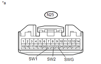
*a |
Front view of wire harness connector (to Navigation Receiver Assembly) |
| OK | .gif) |
PROCEED TO NEXT SUSPECTED AREA SHOWN IN PROBLEM SYMPTOMS TABLE |
|
.gif)
|
2. |
INSPECT STEERING PAD SWITCH ASSEMBLY |
(a) Remove the steering pad switch assembly (See page
).
(b) Inspect the steering pad switch assembly (See page
).
| NG | |
REPLACE STEERING PAD SWITCH ASSEMBLY |
|
|
3. |
INSPECT SPIRAL CABLE WITH SENSOR SUB-ASSEMBLY |
(a) Remove the spiral cable with sensor sub-assembly (See page
).
(b) Inspect the spiral cable with sensor sub-assembly (See page
).
| OK | |
REPAIR OR REPLACE HARNESS OR CONNECTOR (NAVIGATION RECEIVER ASSEMBLY - SPIRAL CABLE WITH SENSOR SUB-ASSEMBLY) |
| NG | |
REPLACE SPIRAL CABLE WITH SENSOR SUB-ASSEMBLY |
 Black Screen
PROCEDURE
1.
CHECK DISPLAY SETTING
(a) Check that the display is not in "Screen Off" mode.
OK:
The display setting is not in "Screen Off" mode. ...
 Vehicle Speed Signal Circuit between Radio Receiver and Combination Meter
DESCRIPTION
for Navigation Function:
The navigation receiver assembly receives a vehicle speed signal from
the combination meter assembly and sends the signal to navigation receiver
...
Other materials:
System Description
SYSTEM DESCRIPTION
1. SYSTEM DESCRIPTION
(a) The Electronic Controlled Automatic Transmission (ECT) is an automatic transmission
that has its shift timing electronically controlled by the ECM. The ECM detects
electrical signals that indicate engine and driving conditions, and controls the
sh ...
Transmission Fluid Temperature Sensor "A" Circuit Short To Ground (P071011)
DESCRIPTION
The No. 1 ATF temperature sensor converts the fluid temperature into a resistance
value for use by the ECM.
The ECM applies a voltage to the temperature sensor through terminal THO1 of
the ECM.
The sensor resistance changes with the ATF temperature. As the temperature becomes
hi ...
Tachometer Malfunction
DESCRIPTION
In this circuit, the meter CPU receives engine speed signals from the ECM using
the CAN communication system (CAN V1 Bus). The meter CPU displays the engine speed
calculated based on the data received from the ECM.
WIRING DIAGRAM
PROCEDURE
1.
CHECK CAN CO ...
