Toyota Tacoma (2015-2018) Service Manual: Removal
REMOVAL
PROCEDURE
1. REMOVE FRONT WHEEL
2. INSPECT FRONT SUSPENSION LOWER ARM
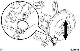
(a) Install the hub nuts onto the disc.
(b) Using a dial indicator, check the lower ball joint for excessive play when you push the hub nuts up and down with a force of 294 N (30 kgf, 66 lbf).
Maximum:
0.5 mm (0.020 in.)
HINT:
If it is not within the specification, replace the lower arm.
3. SEPARATE FRONT SHOCK ABSORBER WITH COIL SPRING
(a) Remove the bolt, nut and washer.
(b) Separate the front shock absorber with coil spring from the suspension lower arm.
4. REMOVE FRONT SUSPENSION LOWER ARM
.png)
(a) Remove the 2 bolts, and separate the front lower ball joint attachment from the front axle.
|
(b) Place matchmarks on the camber adjust cam No. 2 and toe adjust cam. |
|
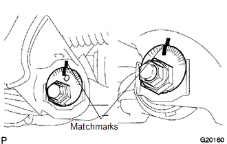
(c) Remove the nut, camber adjust cam No. 2, camber adjust cam No. 1, bolt, toe adjust cam, toe adjust plate No. 2 and front suspension lower arm.
|
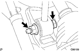
(d) Remove the cotter pin and the nut. |
|
(e) Using SST, remove the front lower ball joint attachment LH.
SST: 09628-00011
 Disassembly
DISASSEMBLY
PROCEDURE
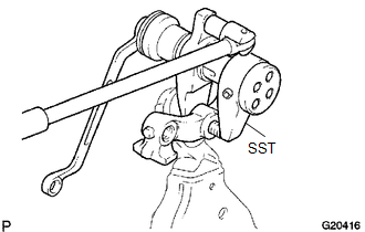
1. REMOVE FRONT LOWER ARM BUSH NO. 1
(a) Using a hammer and chisel, raise the flange of the bush diagonally as shown
in the illustration.
(b) Using SST, remove ...
 Inspection
INSPECTION
PROCEDURE
1. INSPECT FRONT SUSPENSION LOWER ARM
(a) Flip the ball joint stud back and forth 5 times, as shown in the illustration,
before installing the nut.
(b) Using a torque wren ...
Other materials:
Front seats
Bench type seat
Seat position adjustment lever
Separated type seats
Seat position adjustment lever
Driver’s seat lumbar support adjustment
knob (if equipped)
Seatback angle adjustment lever ...
Diameter of the Tire is not Uniform (C1337)
DESCRIPTION
The skid control ECU (brake actuator assembly) measures the speed of each wheel
by receiving signals from the speed sensors. These signals are used for recognizing
whether all 4 wheels are operating properly. Therefore, all wheel signals must indicate
the same speed.
D ...
ABS Warning Light Remains ON
DESCRIPTION
The skid control ECU (brake actuator assembly) is connected to the combination
meter assembly via CAN communication.
If any of the following is detected, the ABS warning light remains on:
The skid control ECU (brake actuator assembly) connectors are disconnected
from the ...
