Toyota Tacoma (2015-2018) Service Manual: Disassembly
DISASSEMBLY
PROCEDURE
1. REMOVE FRONT LOWER ARM BUSH NO. 1
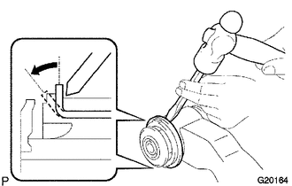
(a) Using a hammer and chisel, raise the flange of the bush diagonally as shown in the illustration.
|
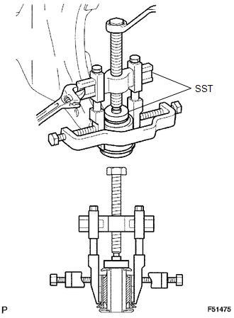
(b) Using SST, remove the lower arm bush. SST: 09950-40011 09951-04010 09952-04010 09953-04020 09954-04010 09955-04011 09957-04010 09958-04011 SST: 09950-60010 09951-00470 |
|
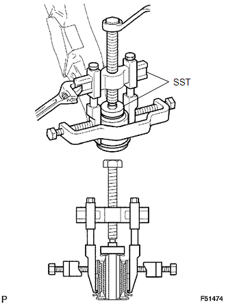
2. REMOVE FRONT LOWER ARM BUSH NO. 2
(a) Using a hammer and chisel, raise the flange of the bush diagonally as shown in the illustration.
|
(b) Using SST, remove the lower arm bush. SST: 09950-40011 09951-04010 09952-04010 09953-04020 09954-04010 09955-04011 09957-04010 09958-04011 SST: 09950-60010 09951-00520 |
|
 Components
COMPONENTS
ILLUSTRATION
...
 Removal
REMOVAL
PROCEDURE
1. REMOVE FRONT WHEEL
2. INSPECT FRONT SUSPENSION LOWER ARM
(a) Install the hub nuts onto the disc.
(b) Using a dial indicator, check the lower ball joint for excessive play w ...
Other materials:
Removal
REMOVAL
PROCEDURE
1. REMOVE FUEL DELIVERY PIPE ASSEMBLY LH (FUEL PRESSURE SENSOR)
(See page )
NOTICE:
Do not remove the fuel pressure sensor from the fuel delivery pipe sub-assembly
LH.
If a fuel pressure sensor is removed, replace the fuel delivery pipe
sub-assembly LH (fu ...
Brake Signal Malfunction (B2284)
DESCRIPTION
This DTC is stored when the brake signal sent via direct line and the brake signal
sent via CAN communication do not match.
HINT:
When the cable is disconnected and reconnected to the negative (-) battery terminal,
the power source mode returns to the state it was in before the ca ...
Registration
REGISTRATION
PROCEDURE
1. DESCRIPTION OF CODE REGISTRATION
(a) w/ Wireless Door Lock Control System:
The key has 2 codes: the key code (immobiliser code) and the wireless code. Both
of these codes need to be registered. For the wireless code registration procedures,
refer to Wireless Door Lo ...
