Toyota Tacoma (2015-2018) Service Manual: Removal
REMOVAL
PROCEDURE
1. PRECAUTION
NOTICE:
After turning the ignition switch off, waiting time may be required before disconnecting the cable from the negative (-) battery terminal. Therefore, make sure to read the disconnecting the cable from the negative (-) battery terminal notices before proceeding with work.
Click here .gif)
2. DISCONNECT CABLE FROM NEGATIVE BATTERY TERMINAL
NOTICE:
When disconnecting the cable, some systems need to be initialized after the cable is reconnected.
Click here
3. REMOVE FRONT CONSOLE BOX
Click here
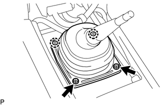
4. REMOVE SHIFT LEVER BOOT ASSEMBLY
|
(a) Remove the 2 screws, 2 clips and shift lever boot assembly. |
|
5. REMOVE FLOOR SHIFT SHIFT LEVER ASSEMBLY
|
(a) Detach the shift lever cap boot from the manual transmission. |
|
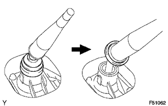
(b) Cover the shift lever cap with a cloth.
|
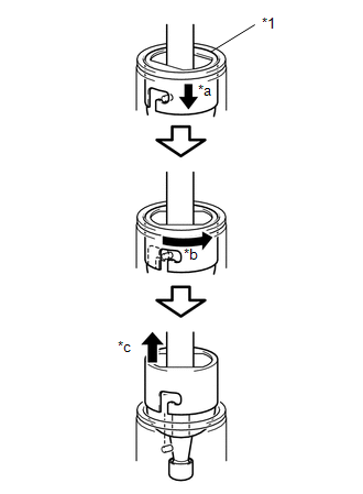
(c) While pressing down on the shift lever cap, turn it counterclockwise, and then pull to remove the shift lever. Text in Illustration
|
|
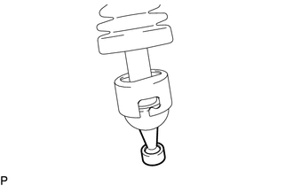
6. REMOVE NO. 1 FLOOR SHIFT BUSH
|
(a) Remove the No. 1 floor shift bush from the floor shift shift lever assembly. |
|
7. DRAIN MANUAL TRANSMISSION OIL
Click here
8. REMOVE FRONT EXHAUST PIPE ASSEMBLY
Click here
9. REMOVE MANIFOLD STAY
Click here
10. REMOVE NO. 2 MANIFOLD STAY
Click here
11. REMOVE STARTER ASSEMBLY
Click here
12. REMOVE PROPELLER SHAFT WITH CENTER BEARING ASSEMBLY
Click here
13. REMOVE FRONT DIFFERENTIAL CARRIER ASSEMBLY
Click here
14. SUPPORT MANUAL TRANSMISSION ASSEMBLY
(a) Support the manual transmission with a transmission jack.
NOTICE:
- Make sure the high transmission jack attachment is centered on the safety stand.
- Secure the part with a rope, attachment, etc.
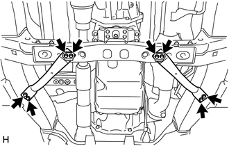
15. REMOVE FRONT SUSPENSION MEMBER BRACKET LH AND RH
|
(a) Remove the 8 bolts, front suspension member bracket LH and front suspension member bracket RH from the No. 3 frame crossmember sub-assembly and vehicle body. |
|
16. REMOVE NO. 3 FRAME CROSSMEMBER SUB-ASSEMBLY
|
(a) Remove the 4 bolts on the No. 3 frame crossmember sub-assembly. |
|
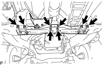
(b) Remove the 4 nuts, 4 bolts and No. 3 frame crossmember sub-assembly.
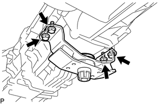
17. REMOVE REAR NO. 1 ENGINE MOUNTING INSULATOR
|
(a) Remove the 4 bolts and rear No. 1 engine mounting insulator from the manual transmission assembly. |
|
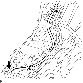
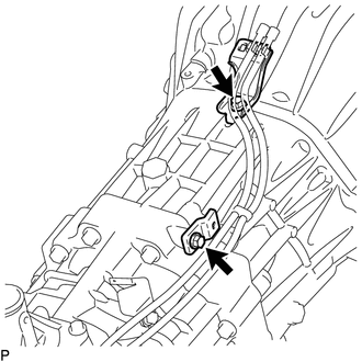
18. DISCONNECT WIRE HARNESS
|
(a) Disconnect the 3 connectors and wire harness. |
|
(b) Detach the 10 clamps to separate the wire harness.
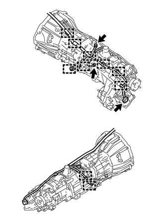
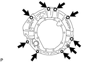
19. REMOVE MANUAL TRANSMISSION ASSEMBLY
|
(a) Remove the 9 bolts and manual transmission assembly. NOTICE: As the manual transmission assembly is very heavy, be sure to support it securely. |
|
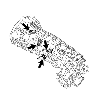
20. REMOVE TRANSMISSION BREATHER SUB-ASSEMBLY
|
(a) Detach the 3 breather hose clamps. |
|
(b) Remove the transmission breather sub-assembly from the control shift lever retainer assembly.
|
(c) Remove the 2 bolts and 2 brackets. |
|
21. REMOVE WIRING HARNESS CLAMP BRACKET
|
(a) Remove the 4 bolts and 4 wiring harness clamp brackets. |
|
22. REMOVE TRANSFER ASSEMBLY
Click here
 Installation
INSTALLATION
PROCEDURE
1. INSTALL TRANSFER ASSEMBLY
Click here
2. INSTALL WIRING HARNESS CLAMP BRACKET
(a) Install the 4 wiring harness clamp brackets with the 4 bolts.
Torque:
8.0 N·m {82 ...
 Manual Transmission Oil
Components
COMPONENTS
ILLUSTRATION
On-vehicle Inspection
ON-VEHICLE INSPECTION
PROCEDURE
1. INSPECT MANUAL TRANSMISSION OIL
(a) Park the vehicle on a level surface.
(b) Remove the transm ...
Other materials:
Speaker Output Short (B15C3)
DESCRIPTION
This DTC is stored when a malfunction occurs in the speakers.
DTC No.
DTC Detection Condition
Trouble Area
B15C3
A short is detected in the speaker output circuit.
Harness or connector
Speaker
...
Components
COMPONENTS
ILLUSTRATION
*1
COWL TOP VENTILATOR LOUVER SUB-ASSEMBLY
*2
FRONT FENDER UPPER PROTECTOR LH
*3
FRONT FENDER UPPER PROTECTOR RH
*4
FRONT WIPER ARM HEAD CAP
*5
WINDSH ...
Black Screen
PROCEDURE
1.
CHECK DISPLAY SETTING
(a) Check that the display is not in "Screen Off" mode.
OK:
The display setting is not in "Screen Off" mode.
NG
CHANGE SCREEN TO SCREEN ON MODE
OK
...
